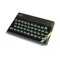
Sinclair ZX Spectrum Service Manual
Spectrum For Everyone https://spectrumforeveryone.com/
13
1.6 INPUT/OUTPUT
The input/output section of the Spectrum is centered round the ULA (IC1). The functions performed within
the device include TV video compilation, keyboard scanning and tape input/output. It also derives and
controls the CPU clock (CPU) using an external 14 MHz crystal X1, and drives the loudspeaker when a
‘BEEP’ instruction is being executed. Each of these sections and the supporting circuits are described
below.
1.7 TV PICTURE GENERATION
The video compilation section of the ULA operates in conjunction with the memory mapped picture
display area in the standard 16k RAM, the colour (chrominance) modulator (IC14) and the UHF modulator.
This combination produces a high resolution, 24 line x 32 character, eight colour TV display.
Using the 14 MHz clock the ULA derives line and field timing compatible with the external TV receiver.
Video is derived by accessing the memory mapped display area in the RAM in a set sequence at set times
throughout the picture frame. The addresses are necessarily independent of the CPU and appear on the
ULA address lines A6 through A0 as two separate bytes timed by the RAS/CAS row/column address select
lines.
The net result is three separate video waveforms outputs from the ULA on pins 15, 16 and 17. These carry
the luminance signal Y, incorporating the line and field sync, and two unmodulated colour difference
signals U and Y making the Spectrum compatible with both colour and monochrome receivers.
From the ULA, the colour difference signals are applied to the colour modulator IC14 via two level shifting
networks. These match the ULA output levels with those required by the B-Y and R-Y inputs to the
modulator. In the Issue 2 Spectrum the level shifting network is passive, incorporating two potentiometers
VR1, VR2. These are required to set-up the chroma bias level on IC14 pin 3 such that the voltage difference
measured between pin 3 and the colour difference signals on pins 2 and 3 respectively in nominally 0V dc.
In the Issue 3 Spectrum two active networks incorporating TR8 and TR9 eliminate the potentiometers,
greatly improving colour stability.
The level shifted colour difference signals, input to IC14, are then encoded, by quadrature modulating two
4.43 MHz chroma sub-carriers. The sub-carriers are generated with the assistance of an external crystal
X2 and a CR lead/lag network introducing a 90 degrees phase shift between pins 1 and 18. (A further
difference between the Issue 2 and 3 Spectrums lies in the bias oscillator. The early issues incorporate a
trimmer TC2 allowing the chroma sub-carrier frequency to be adjusted; on the later issues the frequency
is fixed). The resultant modulated colour difference signals are finally mixed producing a composite
chroma sub-carrier at IC14 pin 13.
At this point the chroma signal is ac coupled to the base of TR2 and added to the inverted luminance signal
on TR1 collector. The resultant composite video is then buffered and applied to an encapsulated UHF
modulator operating on European standard channel 36.

 Loading...