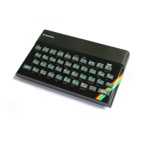
Sinclair ZX Spectrum Service Manual
Spectrum For Everyone https://spectrumforeveryone.com/
25
5 FAULT DIAGNOSIS AND REPAIR – PSU AND MEMORY
Fault Diagnosis
Techniques
Power Supply Unit
Initialisation
Memory Check
Keyboard Structure
5.1 FAULT DIAGNOSIS TECHNIQUES
In a closed loop system such as a computer, because of the interdependence of numerous component
parts, fault diagnosis is not necessarily straight-forward. In addition, because of the high speed cyclic
operation, interpretation of any waveforms on control, data and address lines as being valid depends to
a large extent on practical experience of the system. There are however, certain checks with valid
waveforms and levels that can be carried out before substituting any integrated circuits. Experience has
shown that the best method of initially checking waveforms and levels can be to compare with the same
point in a known serviceable board. The following pages provide a basic fault-finding procedure and
furnish a list of possible faults along with suggested ways of curing them.
With a densely populated board such as the ZX Spectrum, as careful physical examination of the board
can sometimes indicate an obvious fault. Burnt-out discrete components or an overheated track show up
immediately, as do the attentions of an enthusiastic amateur. Bearing in mind the latter, short circuits
caused by hairline solder `splatter` can be of several ohms resistance and can cause some very misleading
fault symptoms.
Providing first principles are adhered to and a common-sense approach is adopted, it will be found after
a short space of time that fixing a faulty Spectrum is very much a routine operation.
5.2 POWER SUPPLY UNIT
The unstabilised external power supply unit is a source of some problems. The design is such that, at
minimum input voltage (215 ac) and 1.4A output, the voltage through should not be less than 7.0V; at
maximum input voltage (265 ac) and 600mA output. the voltage peak should be less than 14V.

 Loading...