Sinclair ZX Spectrum Service Manual
Spectrum For Everyone https://spectrumforeveryone.com/
18
3.1.3 Colour Adjustment
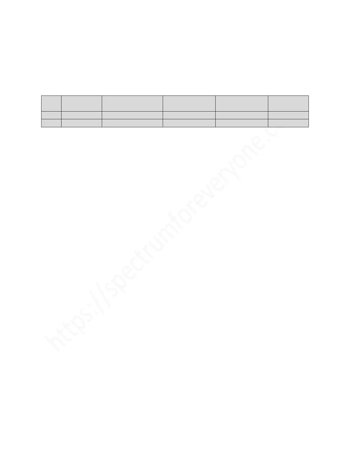
Potentiometers VR1 and VR2 are used to effectively null the voltages between pins 4 and 2 (for VR1) and
pins 2 and 3 (for VR2) on IC14 (LM1889). To allow for thermal drift, the potentiometers are set for non-
zero voltages; furthermore, these voltage off-sets are set to satisfactory but non-optimum levels in
production, and optimum values may be used to advantage in servicing. The relevant figures are given in
the following table - voltages are given relative to pin 3 of LM1889.
3.1.4 Sub-Carrier Oscillator
The chrominance sub-carrier oscillator frequency should be 4.433619 MHz +/- 50 Hz. This frequency may
be checked/adjusted by using one of two methods, listed in (1) or (2) below.
Apply power to the power socket using a bench power supply set at 9V. Current consumption will be
approximately 500mA to 700mA for the 16k Spectrum and 700mA to 900mA for the 48k Spectrum.
1. Feed the Spectrum modulator output via a co-axial cable into a standard colour TV receiver.
Measure the frequency of the locked TV chroma sub-carrier.
2. Connect pin 17 of IC14 (LM1889) via a 4.7pF capacitor and a lead to the frequency meter. It is
recommended that this is done using a jig made up from an IC test clip. Pin 18 of this chip must
be removed to minimise stray capacitance. Connect a 10k ohm resistor between the input
terminals of the frequency meter. Measure the frequency and adjust trimmer TC2 if the measured
frequency is outside tolerance.
3.1.5 14 MHz Oscillator
This frequency is not readily set by working to a specified frequency and tolerance. On Issue 2 boards
trimmer TC1 should be adjusted to minimise the effects of beat frequencies which cause waves of
distortion to flow across the screen. These are particularly apparent with certain colour combinations, e.g.
red INK or green PAPER, and the phenomenon is sometimes referred to as `dot crawl`. It is stressed that
adjustment of this frequency is not straight-forward, as deviations due to temperature change are easily
visible; tuning should be adjusted to minimise rather than remove this effect.
Proceed as follows:
1. Set up the Spectrum to display green PAPER with red INK
2. Type-in three or four lines of characters and monitor the screen.
3. Adjust trimmer TC1 to minimise the effects of distortion.

 Loading...


