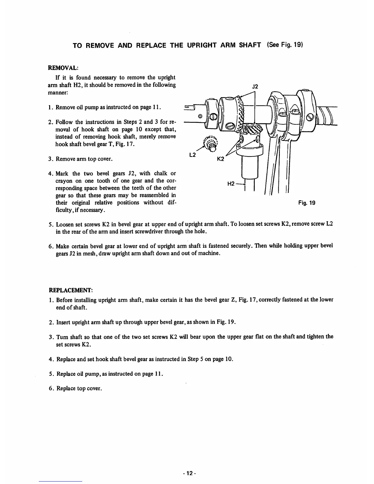
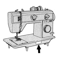
TO REMOVE AND REPLACE THE UPRIGHT ARM
SHAFT
(See Fig. 19)
REMOVAL:
If it is found necessary to remove the upright
arm shaft H2, it should be removed in the following
manner:
1. Remove oil pump as instructed on page 11.
2. Follow the instructions in Steps 2 and 3 for re
moval
of
hook
shaft on page 10 except
that,
instead
of
removing
hook
shaft, merely remove
hook
shaft bevel gear T, Fig.
17.
3.
Remove
arm
top
cover.
4. Mark the two bevel gears
J2,
with chalk or
crayon on one tooth
of
one gear and the cor
responding space between the teeth of the other
gear so that these gears may be reassembled in
their original relative positions without dif
ficulty, if necessary.
Fig. 19
5. Loosenset
screws
K2 in
bevel
gearat upper end of uprightarm shaft. To loosenset
screws
K2,
remove
screwL2
in the rear
of
the arm and insert screwdriver through the hole.
6.
Make
certain
bevel
gear
at lowerend of
upright
arm shaft is
fastened
securely.
Then
while
holding
upper
bevel
gears
J2 in mesh,drawuprightarmshaft downand out of
machine.
REPLACEMENT:
1.
Before
installing upright arm shaft, make certain it has the
bevel
gear Z, Fig.17, correctlyfastened at the lower
end
of
shaft.
2. Insert upright arm shaft up through upper bevelgear, as shown in Fig. 19.
3. Turn shaft so that one
of
the two set screws K2 will bear upon the upper gear flat on the shaft and tighten the
set
screws
K2.
4. Replace and set hook shaft bevel gear as instructed in Step 5 on page 10.
5. Replace oil
pump,
as instructed on page
11.
6. Replace
top
cover.
12-