TO
REMOVE
AND
REPLACE
NEEDLE
BAR
FRAME
ASSEMBLY
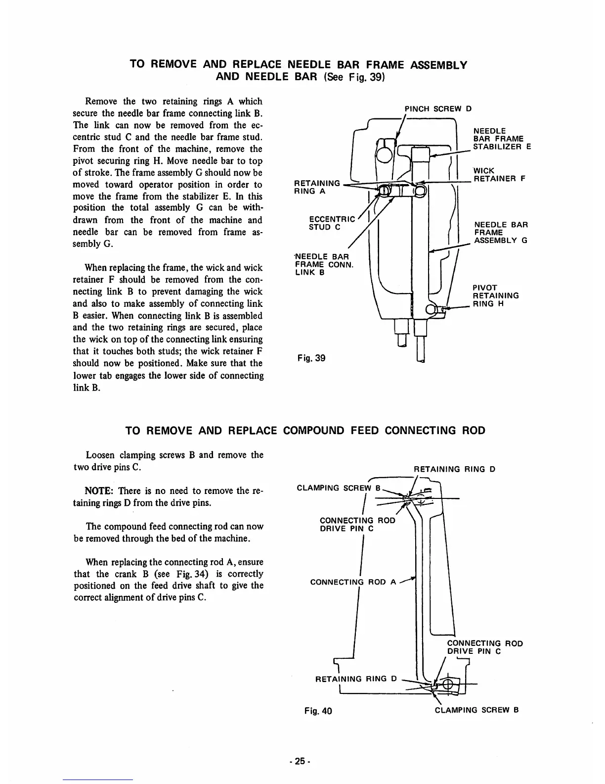
AND NEEDLE BAR (See Fig. 39)
Remove
the
two retaining rings A which
secure the needle bar frame connecting link B.
The
link
can
now
be
removed
from
the
ec
centric
stud
C
and
the
needle
bar
frame
stud.
From
the
front
of
the
machine,
remove
the
pivot securing ring H. Move needle bar to
top
of
stroke. The frame assembly G should
now
be
moved toward
operator
position in
order
to
move
the
frame
from
the
stabilizer
E.
In
this
position the total assembly G can be with
drawn
from
the
front
of
the
machine
and
needle
bar
can
be
removed
from
frame
as
sembly G.
When replacing the frame, the wick and wick
retainer
F
should
be
removed
from
the
con
necting link B to prevent damaging the wick
and
also to make assembly
of
connecting link
B easier. When connecting link B is assembled
and
the
two retaining rings are secured, place
the
wick on
top
of
the connecting link ensuring
that
it
touches
both
studs;
the
wick
retainer
F
should now be positioned. Make sure that the
lower tab engages the lower side
of
connecting
link
B.
RETAINING
RING
A
ECCENTRIC
STUD
C
•NEEDLE
BAR
FRAME
CONN.
LINK
B
Fig.
39
PINCH
SCREW
D
NEEDLE
BAR
FRAME
STABILIZER
E
WICK
RETAINER
F
NEEDLE
BAR
FRAME
ASSEMBLY
G
PIVOT
RETAINING
RING
H
TO
REMOVE
AND
REPLACE
COMPOUND
FEED
CONNECTING
ROD
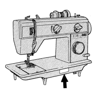
Loosen clamping screws B and remove the
two
drive pins C.
NOTE:
There
is
no
need
to
remove
the
re
taining rings D from
the
drive pins.
The compound feed connecting rod can now
be removed through the bed
of
the machine.
When replacing
the
connecting rod A, ensure
that the crank B (see Fig. 34) is correctly
positioned on the feed drive shaft to give
the
correct alignment
of
drive pins C.
CLAMPING
SCREW
B
CONNECTING
ROD
DRIVE
PIN
C
CONNECTING
ROD
A
RETAINING
RING
D
Fig.
40
-25-
RETAINING
RING
D
CONNECTING
ROD
DRIVE
PIN
C
CLAMPING
SCREW
B