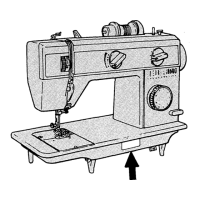
TO
REMOVE
OIL
WICK
HOLDER
(See Fig.
24)
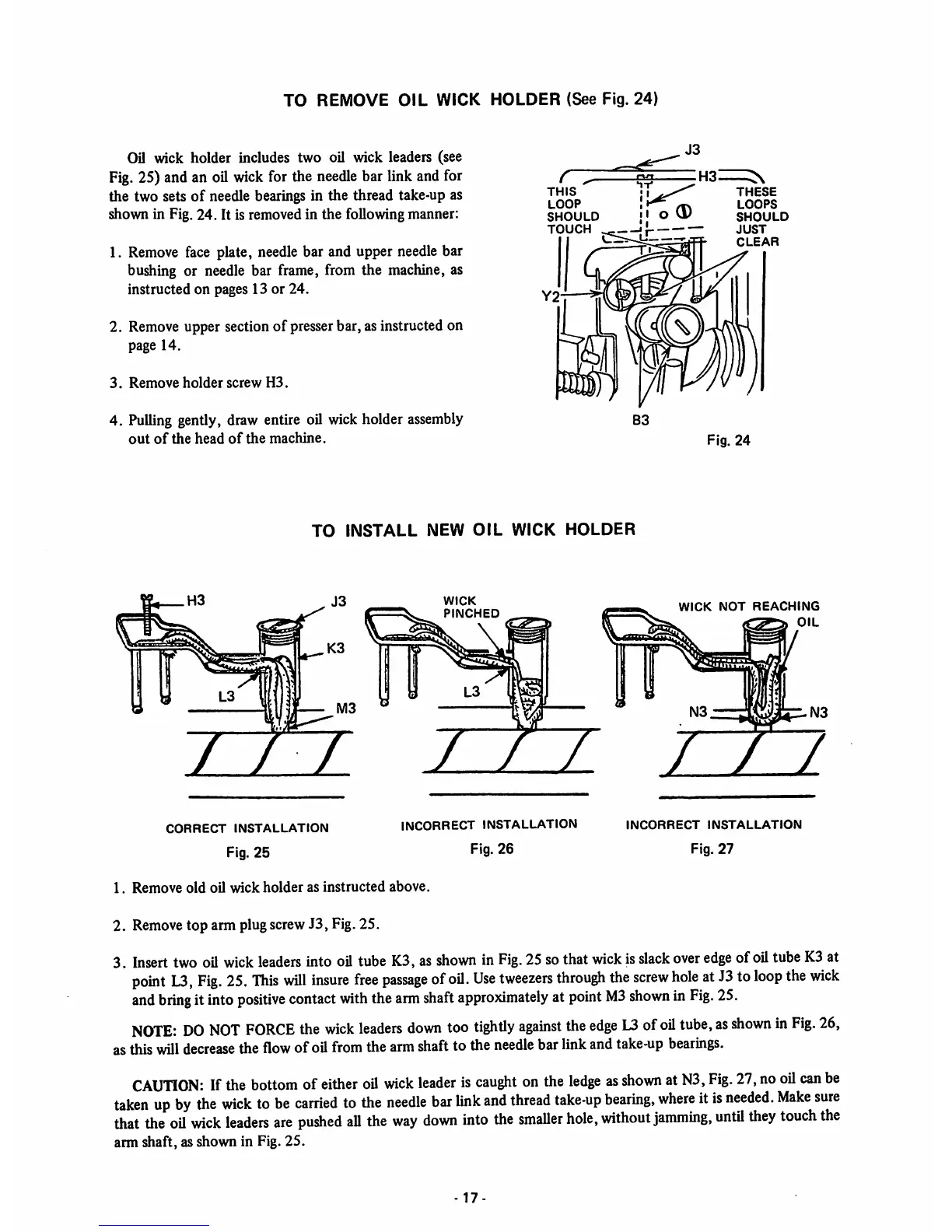
Oil wick holder includes two oil wick leaders (see
Fig. 25) and an oil wickfor the
needle
bar link and for
the two sets
of
needle bearings in the thread take-up as
shown in Fig.
24.
It is removed in
the
following manner:
1. Remove face plate, needle bar and upper needle bar
bushing or needle bar frame, from the machine, as
instructed on pages 13 or
24.
2. Remove upper section
of
presser bar, as instructed on
page 14.
3.
Remove
holder
screw
H3.
4.
Pulling
gently, draw entire oil wickholder
assembly
out
of
the
head
of
the
machine.
THIS
LOOP
SHOULD
TOUCH
THESE
LOOPS
SHOULD
JUST
CLEAR
Fig.
24
TO
INSTALL
NEW
OIL
WICK
HOLDER
i~r-T
CORRECT
INSTALLATION
Fig.
25
WICK
PINCHED
7
INCORRECT
INSTALLATION
Fig.
26
WICK
NOT
REACHING
OIL
TTl
INCORRECT
INSTALLATION
Fig.
27
1.
Remove
old
oil
wick
holder
as
instructed
above.
2.
Remove
top arm plugscrewJ3, Fig.25.
3.
Insert
two
oil
wick
leaders
into
oil
tube
K3,
as
shown
in
Fig.
25sothat
wick
is
slack
over
edge
ofoil
tube
K3
at
point
L3,
Fig.
25.
This
will
insure
free
passage
of
oil.
Use
tweezers
through
the
screw
hole
at
J3
to
loop
the
wick
and
bring
it
into
positive
contact
with
the
arm
shaft
approximately
at
point
M3
shovm
in
Fig.
25.
NOTE:
DO
NOT
FORCE
the
wick
leaders
down
too
tightly
against
the
edge
L3
of
oil
tube,
as
shown
in
Fig.
26,
as
this
will
decrease
the
flow
ofoil
from
the
arm
shaft
to the
needle
bar
link
and
take-up
bearings.
CAUTION:
If
the
bottom
of
either
oil
wick
leader
is
caught
on
the
ledge
as
shown
at
N3,
Fig.
27,
no
oil
can
be
taken
up
by
the
wick
to
be
carried
to
the
needle
bar
link
and
thread
take-up
bearing,
where
it
is
needed.
Make
sure
that
the
oil
wick
leaders
are
pushed
all
the
way
down
into
the
smaller
hole,
without
jamming,
untU
they
touch
the
arm
shaft, as shown in Fig.
25.
17-