To replace the piesser bar:
1. Slip presserbar down through lifting leverlink H, Fig. 20 and lower presser bar bushing.
2.
Replace
presser
foot and
presser
bar
pressure
regulating
thumb screwR2with
presser
bar
guide.
3.
Set presser bar at correct height, as instructed on page 4, and tighten screw J.
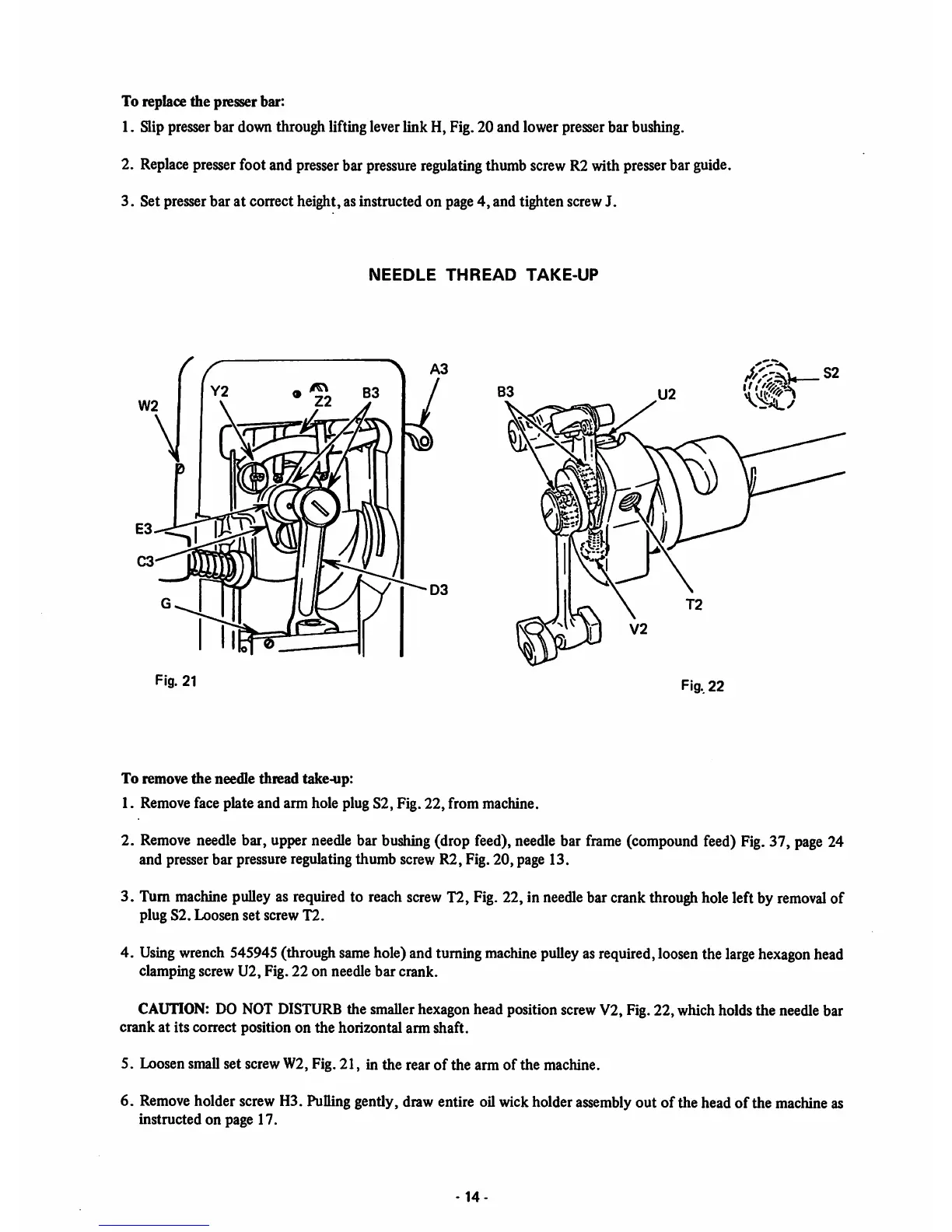
NEEDLE
THREAD
TAKE-UP
Fig. 21
Fig..
22
U2
To remove
the
needle thread takemp:
1. Removeface plate and arm hole plug S2, Fig. 22, from machine.
2.
Remove
needlebar, upper needlebar bushing(drop feed), needle bar frame (compound feed) Fig.37, page24
and presserbar pressureregulatingthumb screw R2, Fig. 20, page 13.
3. Tum machine pulley as required to reach screwT2, Fig. 22, in needlebar crankthroughhole left by
removal
of
plug S2. Loosen set screw T2.
4.
Using
wrench
545945(through
same
hole)and turning
machine
pulley
asrequired,loosenthe
large
hexagon
head
clamping screw U2, Fig. 22 on needle
bar
crank.
CAUTION:
DO NOT DISTURBthe smallerhexagon head position screwV2, Fig. 22, which holds the needle bar
crank at its correct position on the horizontal arm shaft.
5. Loosen small set screw W2, Fig.
21,
in the rear
of
the arm
of
the machine.
6.
Remove
holder screw H3. Pullinggently, draw entire oilwick holder assembly out of the head
of
the machineas
instructed
on
page 17.
-14