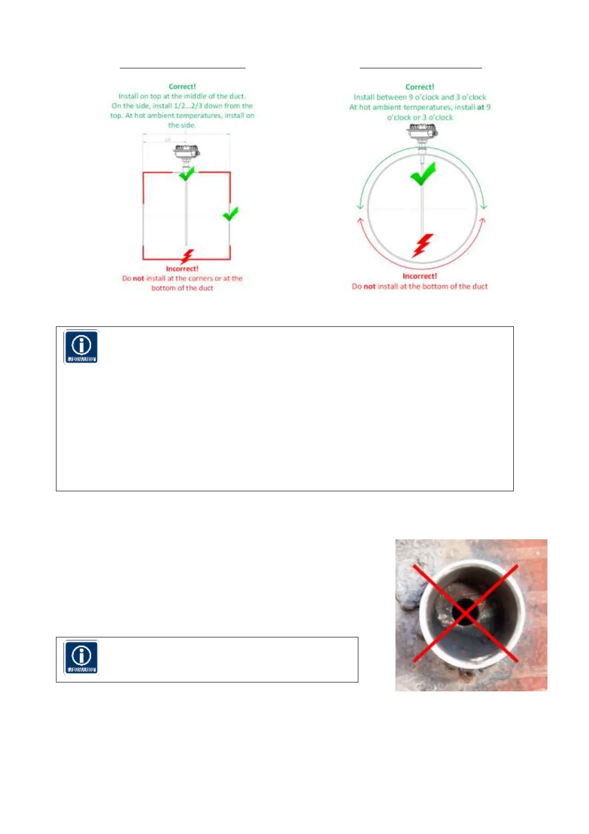
Installation in a square duct
Figure 6 Installation in a squared duct
Installation in a round duct
Figure 7 Installation in a round duct
The sensor must not contact the opposite wall or any other obstacle inside the duct.
The only allowed interaction with the sensor are dust particles.
The unit shall be installed in a position, where the gas flow passes the sensor rod at a
90 angle.
Although the sensor is not affected by vibration, very high vibration levels should be
avoided.
If possible the unit shall be installed in a position where the duct pressure is negative.
If installed downstream an electrostatic precipitator (ESP), the distance from the ESP
should be at least 40 m.
In case of occasional condensation conditions (droplets in the gas) it is recommended
to install the sensor rod showing approximately 5 Deg. downward to avoid liquids
cumulating at the S201 or S203 insulation.
6.2 Installing the sensor
Once the location of the unit has been selected, the mounting socket must
be welded to the pipe or duct. To do this, first cut a hole in the duct
slightly larger than the OD of the mounting socket, 35 mm. The socket
must be perpendicular to the flow in the duct. Make sure the socket is in
the right position and make an airtight welding
After welding the socket in position, insert the sensor.
The diameter of the hole must be minimum 35mm
Figure 8 Wrong socket installation
 Loading...