40
Ref. No. Description SIP Part No. Ref. No. Description SIP Part No.
69. Spindle shaft WD01-00888 92. Washer WD01-00901
70. Bearing 6005 WD01-00889 93. Arbor MT2 66633
71. Bearing ring WD01-00890 94. Chuck WD01-00789
72. Screw (M8 x 25) WD01-00891 95. Table WD01-00902
73. Casting WD01-00892 96. Table arm WD01-00903
74. Label WD01-00893 97. Bolt (M16 x 30) WD01-00854
75. Lock washer WD01-00725 98. Spring washer M16 WD01-00853
76. Clip WD01-00724 99. Lock handle WD01-00904
77. Screw (M5 x 6) WD01-00894 100. Worm pin WD01-00850
78. Tension spring WD01-00842 101. Table support WD01-00849
79. Tension spring cover WD01-00841 102. Bolt (M6 x 12) WD01-00905
80. Nut M12 WD01-00821 103. Crank handle WD01-00906
81. Switch box WD01-00910 104. Circlip WD01-00742
82. Switch WD01-00895 105. Worm shaft WD01-00911
83. Screw (M3 x 10) WD01-00896 106. Worm gear WD01-00848
84. Mains lead clamp WD01-00700 107. Locking handle WD01-00852
85. Mains lead WD01-00720 108. Angle label WD01-00851
86. Indicator WD01-00897 109. Chuck guard 55mm 07662
87. Circlip WD01-00787 110. Drift key WD01-00862
88. Bearing 6203 WD01-00714 111. Hex. Wrench 4mm WD01-00737
89. Quill WD01-00898 112. Hex. Wrench 6mm WD01-00861
90. Spindle WD01-00899 113. Spindle pulley nut (M24 x 1.5) WD01-00907
91. Bearing 6006 WD01-00900
21
OPERATING INSTRUCTIONS
SETTINGS & ADJUSTMENTS
020
021
022
023
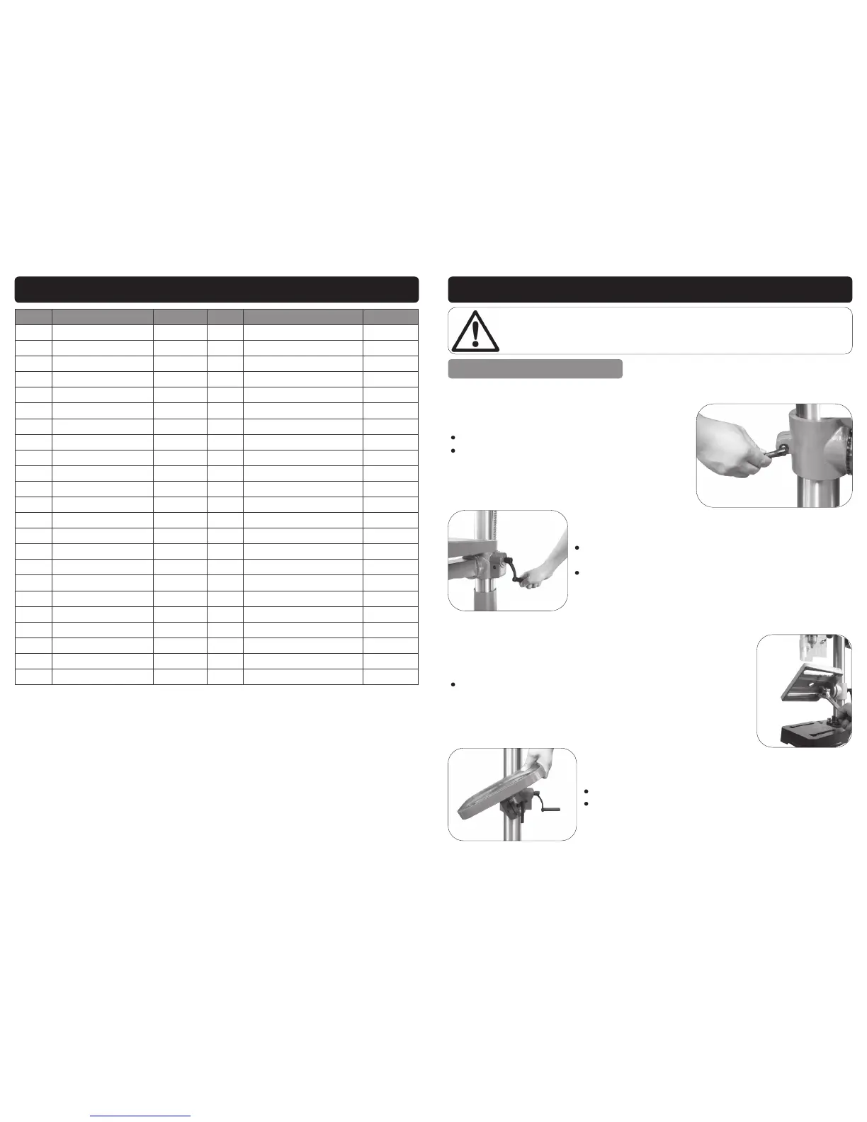
Loosen the table height lock (020).
For the 01700, simply slide the table up/down to
the desired height and re-tighten the table
height lock.
For all other models; Rotate the table height adjustment
handle until the table is at the required height (021).
Re-tighten the table height lock.
Setting The Table Height:
Setting The Table Angle:
The table angle can be adjusted by loosening the table an-
gle lock located underneath the table (022).
Rotate the table to the desired angle (023).
Re-tighten the angle lock.
Danger: Before making any changes or adjustments, ensure that the drill is
turned off, and the mains lead is removed from the supply socket.
 Loading...