ASSEMBLY STEPS
16
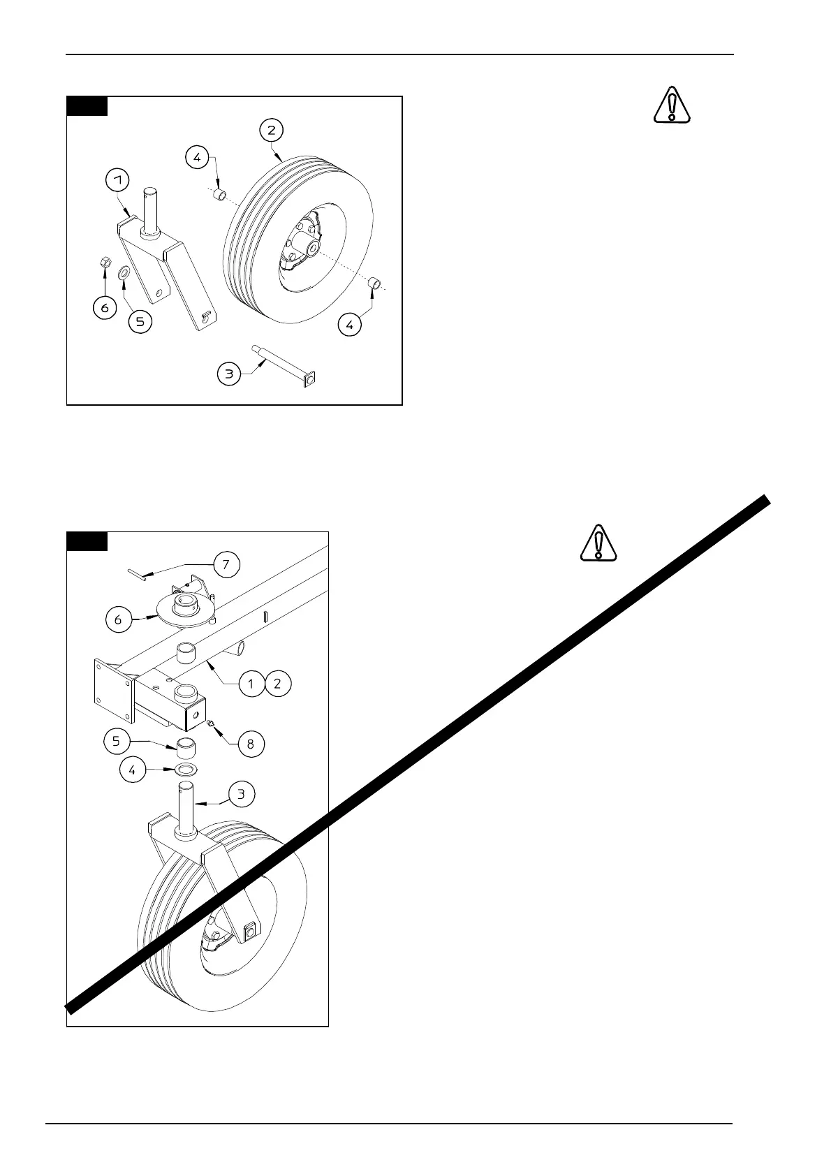
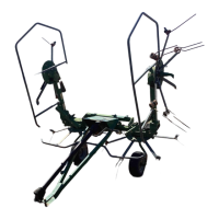
10. CAUTION
Mount wheel-hub assembly 2 on bracket
1 using pin 3, spacers 4, washer 5 and
nut 6.
in this step, you will use:
Item 3:
2 - pins D 30 x 270
(D 1" 13/16 x 10" 5/8)
Item 4:
4 - spacers D 30-38 x 30
(D 1" 3/16 - 1" 1/2" x 1" 3/16 )
Item 5:
2 - washers D 23-50 x 4
(D 7/8" - 2" x 5/32")
Item 6:
2 - nuts M 22 (7/8").
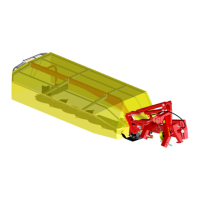
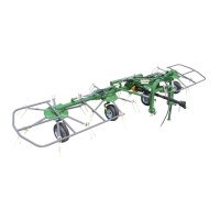
11. ATTENTION
Insert bushings 5 in the holes in sections 1 & 2 (LH -
RH) shown in the illustration. Place the antifriction
washer 4 on the pin of wheel assembly 3, and insert
the wheel assembly pin in the correct holes in
sections 1 & 2 (LH - RH) and secure it with the
flanged bushing 6 and the spring pin 7. Attach
grease nipples 8 to the correct holes of sections 1 &
2 (LH - RH).
In this step, you will use:
Item 4:
2 - washers D 50-76 x 5
(D 2"-3" x 3/16")
Item 5:
4 - bushings D 50-60 x 50
(D 2"-2" 3/8 x 2")
Item 7:
2 - spring pins D 10 x 80
(D 13/32" x 3" 5/32)
Item 8:
2 - grease nipples M 8
(5/16")
SEE PAGE 53
11
10