ASSEMBLY STEPS
30
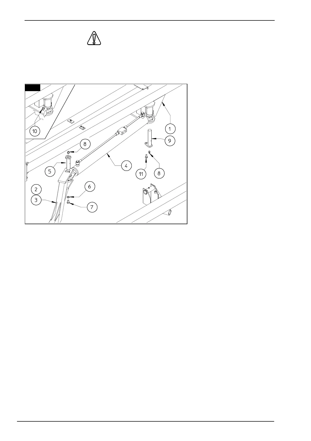
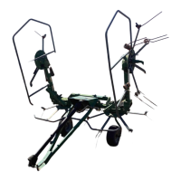
28. ATTENTION
Fit cylinders 4 into the correct places on drawbar 1 and fixed arms 2 & 3 (LH - RH). Fasten
cylinders 4 to drawbar 1 with pins 9 and screws 12. Attach grease nipples 8 to pins 9. When
screw 11 is fastened, attach self-locking nut 10 to screw 12 as show in figure, to prevent pin 9
to go out if screw 11 is
loosened.
Fasten cylinders 4 to fixed
arms 2 & 3 (LH - RH) with
pins 5, washers 6 and screws
7. Attach grease nipples 8 to
pins 5.
In this step, you will use:
Item 5:
2 - pins D 30 x 122
(D 1" 3/16" x 4" 13/16")
Item 6:
2 - washers D 12-40 x 4
(D 15/32"-1" 9/16" x 5/32")
Item 7:
2 - screws M 12 x 20
(15/32" x 13/16")
Item 8:
4 - grease nipples M 8
(15/16")
Item 9:
2 - pins D 30 x 162
(D 1" 3/16" x 6" 3/8" )
Item 10:
2 – self-locking nut M 12-
(D 15/32"--)
Item 11:
2 - screws M 12 x 35
(15/32" x 1” 3/8")
28