120 CFM w/PLC and PC systems
REMINDER: PC controller not illustrated however, distributes pilot signals in same sequence as a PLC
controller.
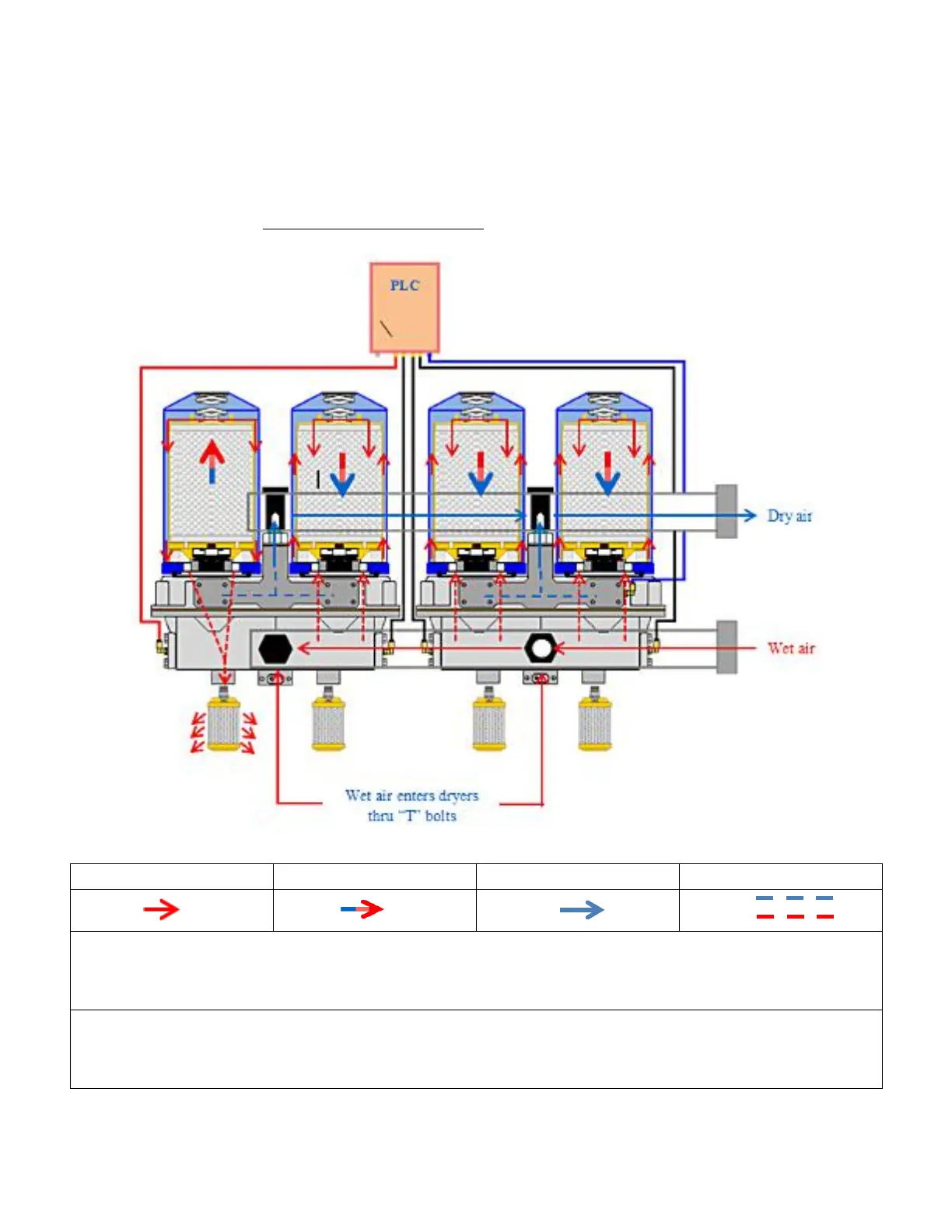
The descriptions detailed on page “Twin Tower w/MLT” schematic represents the sequencing of air flow
as it relates to the actual drying process and transition - wet to dry - within all dryer systems including
Programmable Logic (PLC) and Pneumatically Controlled (PC) systems.
PLC Total Cycle Sequence 180 sec.
Cartridge 1 regenerates for 45 sec. Cartridge 2, 3, 4 receives wet air. PLC switches
Cartridge 2 regenerates for 45 sec. Cartridge 1, 3, 4 receives wet air. PLC switches
PC Total Cycle Sequence 240 sec.
Cartridge 1 regenerates for 60 sec. Cartridge 2, 3, 4 receives wet air. PC switches
Cartridge 2 regenerates for 60 sec. Cartridge 1, 3, 4 receives wet air. PC switches
16