2. Disconnect system air line from manifold
3. Remove black retainer bolts from outlet manifold and remove manifold from dryer unit
4. Discard O-rings between manifolds,
5. Remove the eight (8) socket head bolts fasting manifold to dryer(s) and remove
6. Discard O-rings, springs and regeneration valves
7. Clean valve cavities in housing
8. Position new valve spindles into cavities with spring pockets out
9. Position springs into valves
10. Lubricate new O-rings and install onto manifold bosses
11. Position manifold onto adaptor castings ensuring O-rings are positioned properly in bores.
12. Install eight (8) socket head bolts and tighten to 5-6 in. lbs. Torque.
13. Install new O-rings into recess of manifolds
14. Position outlet manifold onto dryer and reinstall black retainer bolts and tighten to 50 -60 ft. lbs.
torque
15. Reconnect air line to manifold
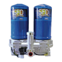
Heater Assembly (if equipped)
110 Volt #619750, 24 VDC #619784, 12 VDC #619782
REMINDER: Heater prevents inlet and purge valves from freezing when SFD mounted in an area
where ambient air temperatures may fall below 32° F (0° C)
1. Disconnect heater lead wire
2. Remove two screws attaching heater connector to casting
3. Remove heater/thermostat assembly and discard
4. Slide new O-ring over heater and thermostat into position around connector flange
5. Apply a light coating of anti-seize to the heater element and thermostat cavity
6. Insert heater element into hole and twist slightly to spread anti-seize
7. Place thermostat into position in cavity and ensure thermostat sits flat in cavity
8. Place foam cube on top of thermostat,
9. Insert the (2) 8-32 x 1/2” screws in heater base inserting one screw through eyelet of ground wire
10. Position heater assembly into position and secure. Reminder: make sure ground wire is secured
11. Reconnect heater
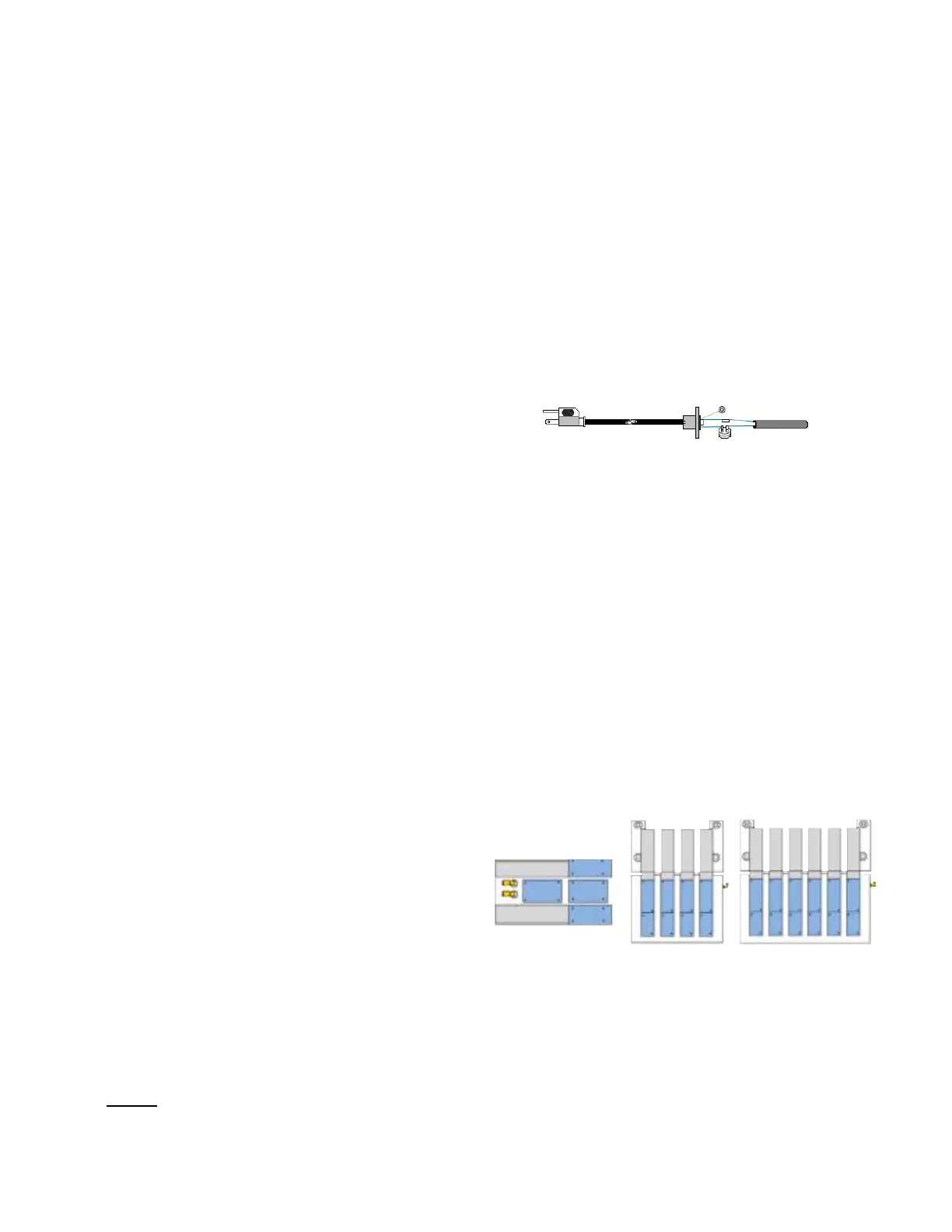
Reset pneumatic control system to home (run) position (40, 80, 120)
#619785,
1. Remove one small valve identified as L25320
from assembly and with regulated air pressure
(35 min – 120 max psi) carefully blow into port 1
2. Remove other small valve identified as L25320
from assembly and with regulated air pressure (35 min – 120 max
psi) carefully blow into port 12
#619787 or #619789
1. Remove one small valve identified as L25320 from assembly and with regulated air pressure (35 min
– 120 max psi) carefully blow into port 12
2. Reinstall valve
3. Slowly Return air pressure to unit and check for 45 second cycles
REMINDER: an erratic cycle may occur, however, should sequence normally after one complete cycle
32