BASIC OPERATION AND INSTALLATION MOUNTING INSTRUCTIONS
Micro Logic Timer (MLT) manages regeneration cycles by
energizing and de-energizing the air control valve at two-
minute intervals. However, when the air dryer is initially
powered on, the MLT begins a startup sequence of four ten-
second cycle intervals, and when completed, MLT begins
cycling every two minutes.
An LED on the MLT will be "on" during energized (charge)
cycle and "off" during de-energized (regeneration) cycle. When
LED is on, the left desiccant cartridge receives wet air and the
right desiccant cartridge regenerates. After two minutes MLT
(dryer) switches, LED is off as left canister now begins regeneration process and right desiccant cartridge
receives wet air. A light flow of air from the desiccant cartridge through dryer’s exhaust port is normal
during regeneration cycle. There should be no venting of air from desiccant cartridge when receiving wet
air.
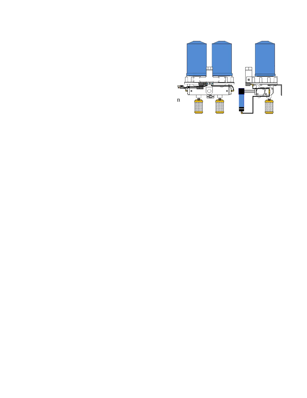
When an SFD cycles, there will be a momentary burst of air from one SFD exhaust port (muffler). This is
normal and will occur each time dryer cycles. Four cartridge MLT systems will have two cartridges
regenerating one from each dryer unit, e.g., cartridges 1, 3 charge cycle, cartridges 2, 4 regeneration cycle
1. SFD dryer systems must be mounted with the exhaust ports positioned downward and desiccant
cartridges in upright position
2. Power source: 120 Volt AC (grounded) surge protected (recommended) electric receptacle
required for MLT and PLC dryer systems
3. Mount SFD down stream of air compressor reservoir
4. Mount SFD dryer with sufficient space around unit(s) to facilitate service and to provide visual
access for periodic inspection allowing at least a 2" clearance above desiccant cartridges for
removal
5. Installing a series of lines and shut-off valves in conjunction with installation of SFD dryer
systems provides a by-pass system providing the ability to maintain operation of air system, when
servicing unit
40 Max SFD Dryer Systems w/ MLT
Mounting
1. Determine proper location for SFD as described in “General Mounting Instructions” pg. 7
2. Universal mounting brackets may be inverted to adapt for mounting units as required
3. Mount base assembly at chosen location making certain a minimum 2" clearance above desiccant
cartridges for future service. Mark mounting hole locations and attach SFD to mounting location
with a minimum of two (2) 3/8” bolts, lock washers and nuts
4. Use thread sealant on air line fittings to prevent air leaks
a. Connect air line coming from compressor reservoir to SFD inlet port
b. Connect SFD outlet port to air system
5. Apply an anti-seize (included with dryer) onto muffler threads and install muffler into each
exhaust port of SFD
6. Plug-in MLT power cord to 110 -120 Volt AC grounded receptacle (surge protected
recommended) REMINDER: 12 & 24 VDC MLT’s device are polarity sensitive. MLT will not
operate if power (+) and neutral (-) leads are switched
8