FLOW DIAGRAMS
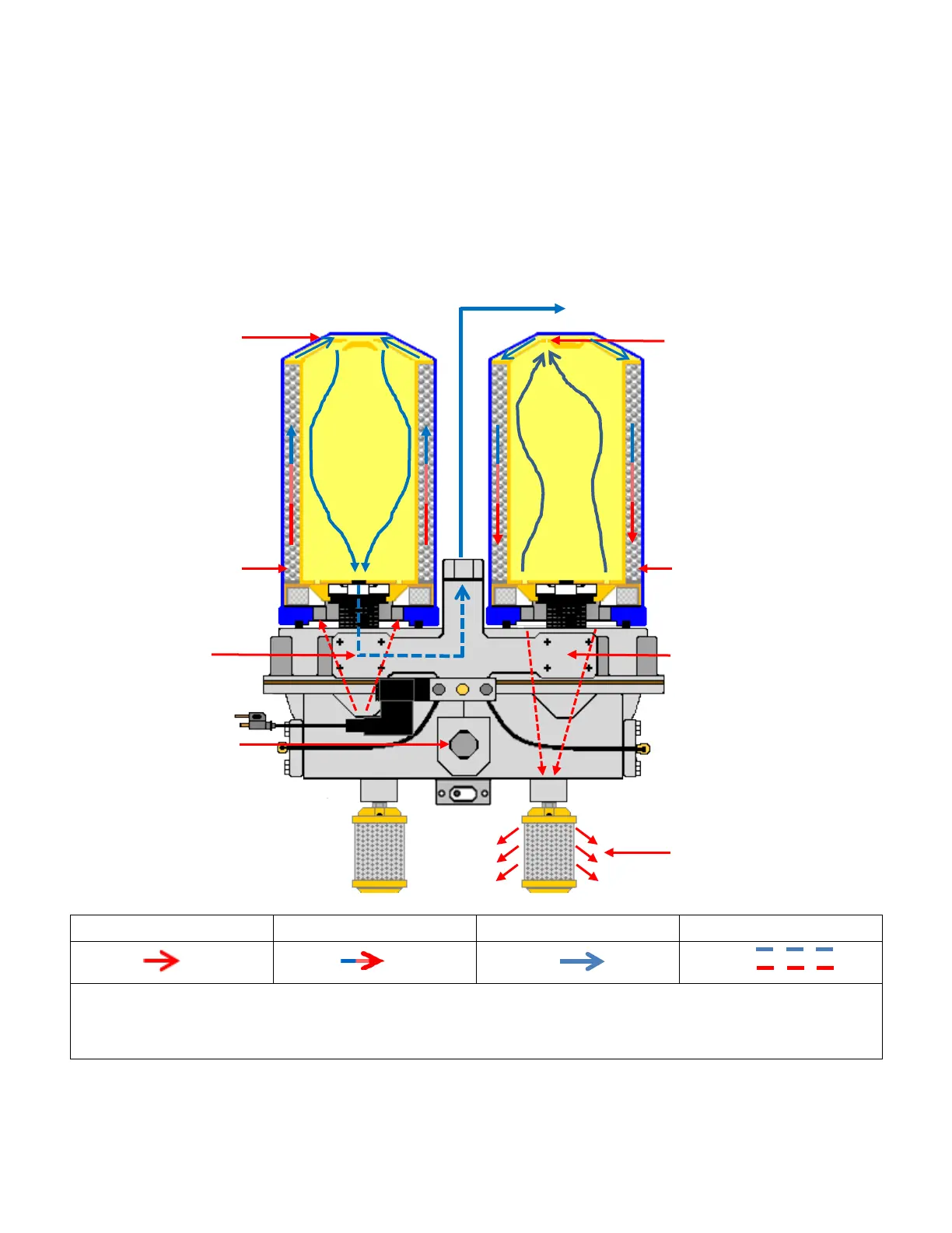
Internal Purge Twin Tower w/MLT
The descriptions detailed in this internal purge schematic represent the sequencing of airflow as it relates
to the actual drying process and transition – wet air to dry air - within all dryer systems including both
Programmable Logic (PLC) and Pneumatically Controlled (PC) systems
Total Cycle Sequence 240 sec.
Cartridge 1 receives wet air for 120 sec. while cartridge 2 regenerates for 120 for sec. - MLT switches
Cartridge 2 receives wet air for 120 sec. while cartridge 1 regenerates for 120 for sec. - MLT switches
1b Outlet Port dried air
flows to system
3b Wet air removed from
"2" desiccant bed
"1" purge reservoir
check valve open
enters dryer
internal reservoir via
orifice
(check valve closed)
2b Check valve
"2" closed
1b Outlet Port wet air
exhausted from dryer
3a Wet air enters
"1" desiccant bed
13