Programmable Logic Control (PLC) Applications (120, 240 400, 600, 800 CFM Dryer Systems)
1. Identify dryer system by counting numbers of desiccant cartridges, e.g., 2, 4, 6
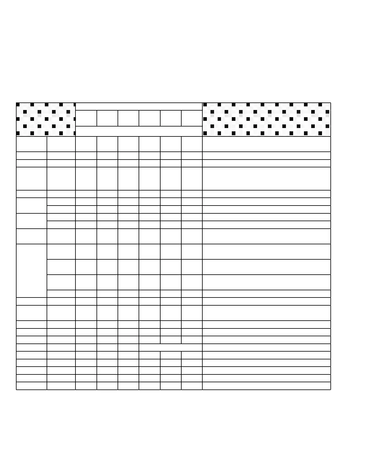
2. Locate service component identity, e.g., A, B, C, etc.
3. Under “Qty”, order appropriate number of kits specific to cartridge total
Qty Qty Qty Qty Qty Qty Descriptions
619704 2 3 4 6 9 12 Desiccant Cartridge Kit
A,I,J 619700 2 3 4 6 9 12
Full Service Kit - includes 2 cartridges, 2 inlet check
valves, 2 purge valves, 1 outlet check valve & 10
micron filter package
Desiccant Cartridge Kit (includes 2 cartridges
Right hand adaptor plate with stud
Left hand adaptor plate with stud
Regeneration Valve Kit (includes 2 .060)
Regeneration Valve Kit (includes 2 .090)
Valve Service Kit - includes 2 inlet check valves, 2
purge valves, 1 outlet check valve
Max 120 cfm .01 prefilter coalescer complete
assembly
Max 200 cfm .01 prefilter coalescer complete
assembly
Max 200 cfm oil coalescing .01 prefilter w/pneumatic
drain service kit
Inlet Check Valve Kit - Includes 2 inlet check valves
M 619990 2 3 4 6 12 24 Wall Mounting Bracket
Not Shown 619775 1 1 1 Moisture Minder
Manifold/Mounting - two dryers (4 cartridges)
Manifold/Mounting - three dryers (6 cartridges)
19