11. Reinstall 8 screws (4 on each side) and torque to 5 – 6 ft. lbs.
12. Reattach the 6 bolts through valve body into adapter plate – do not tighten
13. Reattach 2 ⅜" allen head bolts through adapter plate into valve body
14. Torque all bolts to 50 – 60 ft. lbs.
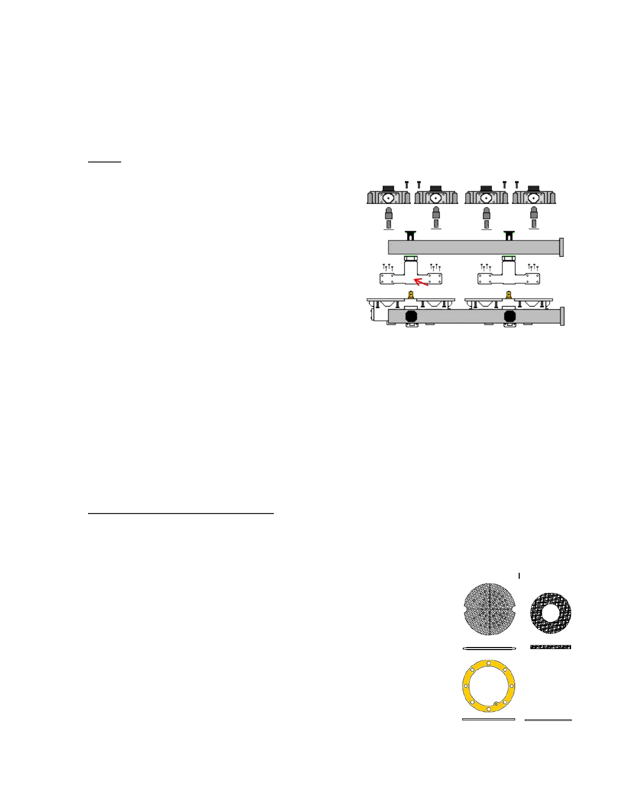
15. Reinstall both regeneration valves and springs into adapter plates
16. Install 2 new O-rings onto shoulders of manifold and install into adapter plates
17. Reinstall 8 screws (4 on each side) into manifold and torque to 5 – 6 ft. lbs.
18. Reconnect air line to outlet port of manifold
19. Slowly apply air pressure and check for leaks
Instructions for 80- 800 cfm air dryer systems
1. WARNING: Relieve all system air pressure
2. Remove air line from outlet port manifold
3. Remove “T” bolts from outlet manifold, remove
manifold and discard green O-rings
4. Remove 8 screws (4 on each side) of dryer manifold,
remove manifold from dryer and discard O-rings
5. Remove spring and regeneration valve from defective
adapter plate and second adapter plate
6. Remove 6 - ⅜" bolts attaching defective adapter plate
to valve body
7. Remove 2 ¼” allen head bolts from top of adapter plate and remove adapter plate, gasket and/or
O-ring
8. Remove all remaining gasket material from valve housing and clean sump of valve house
9. Position gasket and/or O-ring onto valve body
10. Align adapter plate with holes onto valve body
11. Reattach the 6 bolts through valve body into adapter plate – do not tighten
12. Reattach 2 ⅜" allen head bolts through adapter plate into valve body
13. Install new O-rings onto air dryer manifold and position into adapter plates
14. Reinstall 8 screws (4 on each side) and torque to 5 – 6 ft. lbs.
15. Install a new O-ring to connections between manifold and dryer and “T” bolts and manifold
16. Torque bolts attaching new adapter plate to 50 – 60 ft. lbs
17. Torque “T” bolts to 50 – 60 ft. lbs.
18. CAUTION: Slowly pressurize system and check for any air leaks
Desiccant Cartridge, Filter Pad Element and Filter Plate Replacement “F”
#619710, #619860
1. WARNING: Relieve all system air pressure
2. Disconnect air line from inlet port of dryer
3. Using a strap wrench, turn the desiccant cartridge counterclockwise,
remove, and discard
4. Remove and discard O-ring from adapter plate stud and filter elements
5. Remove four (4) 3/8" allen head bolts located at top of adapter plate
castings
6. Remove twelve (12) 3/8" hex head bolts attaching bottom valve housing
to adapter plate castings
7. Remove bottom valve housing assembly
8. Remove two filter plates, gaskets and O-rings (late model version only)
and discard
to Serial # xxxxxx
28