4=24
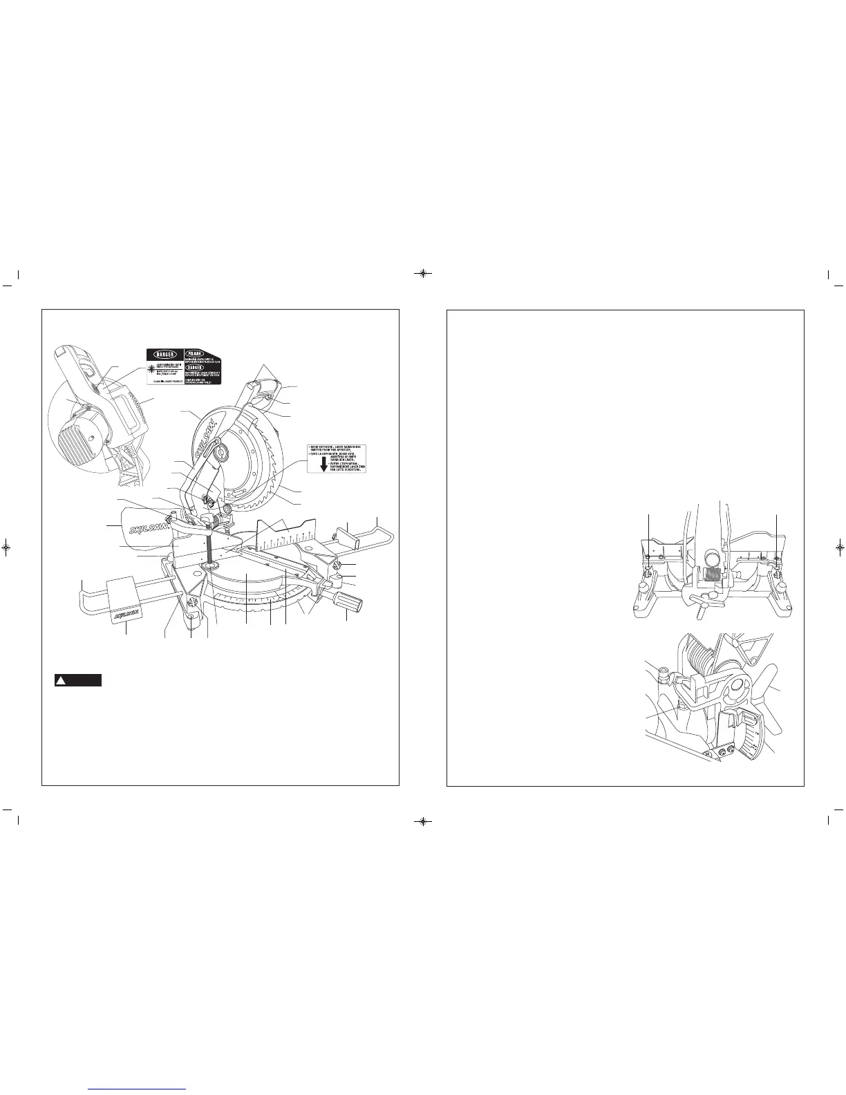
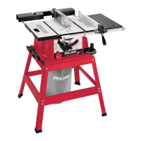
Supports the workpiece. The fence has a cast in scale to
make repetitive cuts easy. The fence also has holes which are
used to secure an auxiliary fence if desired.
4A5=B4AC
Minimizes workpiece tear-out.
)>>;">D=C8=6%03B
Four areas to clamp, bolt or nail the saw to a flat work surface.
+4AC820;;0<?
Provides fast clamping of workpiece.
"8C4A!>2: =>1
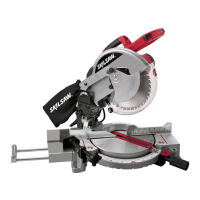
The miter lock knob locks the miter saw table at any desired
miter angle.
!0B4ADC;8=4™
Your miter saw is equipped with a laser cut line to help identify
where the blade will contact the workpiece.
"8C4A(20;4
This scale allows you to read the miter angles easily.
"8C4A4C4=CB0=3"8C4A4C4=C!>2:;4E4A
There are nine (9) miter detents for fast and accurate miter
cuts of common miter angles.
)01;4
Sits in base, provides workpiece support, rotates for desired
miter cuts and rotates the head assembly.
+4AC820;;0<?%>B8C8>=B
There are two (2) positions in the base for the workpiece
clamp.
0B4
Provides working surface to support workpiece.
224BB>AHGC4=B8>=>;4B
Machined holes that accept the extension rail.
GC4=B8>='08;B
Rails used to support long workpieces and table extension.
)01;4GC4=B8>=
This provides extra support and clamping area.
(;838=64=24
Provides maximum height support for the workpiece and
slides to left for easy compound cuts.
!>2:%8=
The compound miter saw is equipped with a lock pin used to
lock the head assembly in the lower position.
!0B4A$=$55(F8C27
Turns the laser alignment system on and off.
78?45;42C>A
This protects against large chips from entering the upper
guard.
!>F4AD0A32CD0C8>=!8=:
Allows for smooth movement of the lower guard.
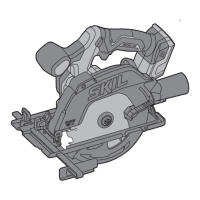
*??4A;034D0A3
Covers upper portion of the blade.
4G,A4=27
Used for tightening/loosening blade and adjusting fence. Hex
wrench is stored in the back of the sliding fence.
(C>?;>2:
Stop block can be used to make repetitive length cuts.
DBC%>AC
The dust port can accommodate the dust bag or a 1-1/4"
vacuum hose hookup.
DBC>;;42C8>=06
Attaches to the dust elbow and collects dust to help keep work
area clean.
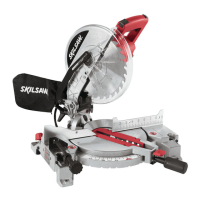
4E4;!>2:0=3;4
The bevel lock handle locks the head assembly at a desired
bevel angle.
P4E4;(C>?
Adjustable stop for a quick and accurate 45° bevel index.
P4E4;(C>?
Adjustable stop for a quick and accurate 0° bevel index.
4E4;(20;4
This scale allows you to read the bevel angles easily.
GC4=B8>='08;!>2: =>1B
Locks the extension rails at desired positions.
&D82:;0<? =>1B
Allows for fast and easy mounting to the Skil miter saw stand.
!>F4AD0A3!8?
Lip can be used to raise the lower guard when guard
becomes jammed on a workpiece.
$'$#)#*)$#$#!((%
4CC8=6)> =>F.>DA"8C4A(0F
)> 0E>83 8=9DAH 5A>< 022 834=C0;
BC0AC8=6 A4<>E4 ?;D6 5A >< ?>F4A
B>DA24>DC;4C145>A4<0:8=60=H039DBC<4=CB
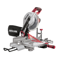
0AAH8=60=3;4
This handle is built into the head assembly for transportation.
A1>A!>2:
Allows the user to keep the blade from rotating while
tightening or loosening arbor screw during blade replacement
or removal.
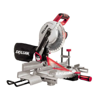
!>2:$55(F8C27
The left or right hand ambidextrous switch must be pressed to
activate the power switch.
(F8C27
The power switch used with the ambidextrous switch
energizes the unit.
(F8C270=3;4
This handle contains the switch. The blade is lowered into the
workpiece by pushing/pulling down on the handle.
!>F4A;034D0A3
The lower blade guard helps protect your hands from the
spinning blade. It retracts as the blade is lowered.
;034
Use only 12
" blades with 1" arbor hole.
WARNING
!