and below work.
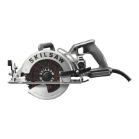
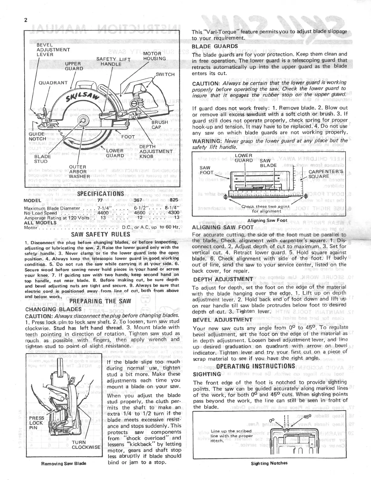
BEVEL
ADJUSTME NT
LEVER MOTOR
SAFETY LIFT HOUSING
UPPER HANDLE
GUARD
SWITCH
OUADRANT
4
\
FOOT
DEP
\
TH
LOWER ADJUSTMENT
BLADE GUARD KNOB
STUD
OUTER
ARBOR
WASHER
SPECIFICATIONS
MODEL 77 367 825
Maximum Blade Diameter
.
.
.
.
7-1/4".
.
.
.
.
6-‘l/2".
.
.
.
8-1/4"
NoLoadSpeed
. . .
. .
.
.
.
..4400
4600
.....4300
Amperage Rating
at
120’Volts.
.
13
.
. .
. .
12
.
.
.
. .
13
ALL
MODELS
Motor
.
.
. .
.
.
.
.
.
.
.
.
.
.
. .
. . . . .
.
D.C.,
or
A.C.up
to
60 Hz.
SAW SAFETY RULES
1. Disconnect
the
plug before changing blades,
or
before
inspecting,
adjusting
or
lubricating the
saw.
2. Raise the lower guard only
with
the
safety handle. 3. Never clamp
or
tie
the lower guard
into
the open
position. 4. Always keep the telescopic lower guard in good working
condition. 5. Do
not
run
the
saw
while
carryingit
at
your
side. 6.
Secure wood before sawing
never
hold pieces in
your
hand
or
across
your
knee. 7.
If
guiding
saw
with
two
hands, keepvsecond hand
on
top handle,
not
near
blade. 8. Before making cut, be
sure
depth
and bevel adjusting
nuts
are
tight and
secure.
9. Always be
sure
that
electric cord is positioned away
from
line
of
cut, both
from
above
PREPARING THE SAW
CHANGING BLADES
CAUTION: Always disconnect theplug before changing blades.
1. Press lock pin
to
lock
saw
shaft. 2. To loosen,
turn
saw
stud
clockwise. Stud has
left
hand thread. 3. Mount blade
with
teeth pointing in direction of rotation. Tighten
saw
stud as
much as possible with fingers, then apply wrench and
tighten stud
to
point
of
slight resistance.
If
the blade slips
too
much
during normal use, tighten
stud a
bit
more.
Make these
adjustments each time you
mount
a blade
on
your
saw.
When
you
adjust the blade
stud properly,
the
cluth per-
mits the shaft
to
make
an
extra
1/4
to
1/2
turn
if
the
blade meets excessive resist-
ance
and stops suddenly. This
protects
saw
components
TURN from "shock overload" and
CLOCKMSE lessens kickback by letting
motor, gears and shaft stop
less abruptly
if
blade should
Removing saw Blade bind
or
jam
to
a stop.
This "Vari-Torque" feature permitsyou
to
adjust blade slippage
to
your
requirement.
BLADE GU AR DS
The blade guards
are
for
your
protection. Keep them clean and
in free operation. The lower guard is a telescoping guard that
retracts
automatically up into the upper guard
as
the blade
enters
its
cut.
CAUTION: Always be certain that the lower guard is working
properly before operating the
saw.
Check the lower guard
to
insure that
it
engages the rubber stop
on
the
upper
gt/am’.
If
guard does
not
work freely: 1. Remove blade. 2. Blow
out
or
remove
all
excess
sawdust with a soft cloth
or
brush. 3.
If
guard still does
not
operate properly, check spring
for
proper
hook-up and tension.
It
may have
to
be replaced. 4. Do
not
use
any
saw
on
which blade guards
are
not
working properly.
WARNING: Never grasp the lower guard
at
any place
but
the
safety
lift
handle.
LOWER
GUAR D SAW
BLADE
SAW
FOOT I CARPENTEITS
;/
SQUARE
Qheic.l< these
two
ppint
for
alignment
Aligning Saw Foot
ALIGNING SAW FOOT
For
accurate
cutting, the side
of
the
foot
must
be parallel
to
the blade. Check alignment
with
carpenter's square. 1. Dis-
""-*-—-
connect
cord. 2. Adjust depth of
cut
to
maximum. 3. Set for
vertical
cut.
4. Retract lower guard. 5. Hold square against
blade. 6. Check alignment with side of the
foot.
If
badly
out
of line, send the
saw
to
your
service center, listed
on
the
back cover,
for
repair.
DEPTH ADJUSTMENT
To adjust
for
depth, set the
foot
on
the edge of the material
with
the blade hanging
over
the edge. 1.
Lift
up
on
depth
adjustment lever. 2. Hold back end of‘
foot
down and
lift
up
on
rear
handle
till
saw
blade protrudes below
foot
to
desired
depth of
cut.
3. Tighten lever.
’
BEV EL ADJUSTMENT
Your
new
saw
cuts
any angle from 0°
to
45°. To regulate
bevel adjustment, set the
foot
on
the edge of the material as
in depth adjustment. Loosen bevel adjustment lever, and line
up desired graduation
on
quadrant
with
arrow
on
bevel
indicator. Tighten lever and try
your
first
cut
on
a piece of
scrap material
to
see
if
you have the right angle.
OPERATING INSTRUCTIONS
SIGHTING
The front edge of the foot is notched
to
provide sighting
points. The
saw
can
be guided accurately along marked lines
of
the work,
for
both 0° and 45°
cuts.
When sighting points
pass beyond the work, the line
can
still be
seen
in
froht
of
the blade.
Line
up
the
scribed
line
with
the
proper
match.
Sighting Notches
 Loading...