114
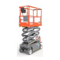
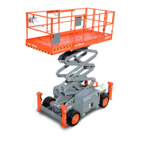
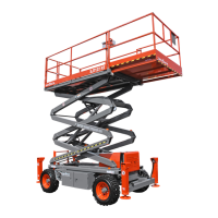
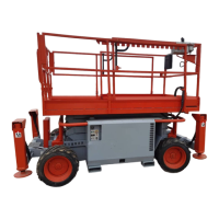
SJ3220, SJ3226, SJ4720, SJ4726, SJ4732223198ABA
Section 4 – Troubleshooting Information Electrical System
4. Loose or broken wire #18 from Torque switch
S27 to Control Module CM1 pin #P3-3.
Check continuity. Test for 24V Input voltage
between wire #18 and wire #02.
Use HMI Diagnostic menu to make sure input P3-3
signal is present.
Replace if defective.
5. Loose or broken wire #18A from Control Module
CM1 pin #P5-9 to Torque Mode Differential valve
coil 2H-18A and/or Torque Mode Speed valve
coils 3H-18A-1 and/or 3H-18A-2 at rear drive
manifold.
Check continuity. Test for 24V Output voltage
between wire #18A and wire #02.
Use HMI Diagnostic menu to make sure output P5-9
signal is present.
Replace if defective.
6. Loose or broken wire #00 from Battery (-) to
Torque Mode Differential valve coil 2H-18A and/or
Torque Mode Speed valve coils 3H-18A-1 and/or
3H-18A-2 at rear drive manifold.
Check continuity. Replace if defective.
7. Defective Torque Mode Differential valve coil
3H-18A.
Check continuity through coil. Replace if defective.
8. Defective Torque Mode Speed valve coil 3H-18A-1 or
3H-18A-2.
Check continuity through coil. Replace if defective.
9. External or internal fault detected by Control Module
CM1.
Check Control Module display screen. Use
Diagnostic Menu to see switch and sensor status.
Correct trouble code as displayed. Replace module
if defective.
4.2-17 Pressure Transducer PT1 Inoperative
1. Control Module CM1 display is broadcasting an
error message.
Check Control Module display screen and follow
instructions to clear error.
2. Loose or broken wire #910 from Control Module
pin #P2-7 to B+(pin1) on Pressure Transducer
PT1.
Check continuity. Test for 24V Output voltage
between wire #910 and wire #902 at P6-4.
Use HMI Diagnostic menu to make sure output P2-7
supply is present.
Replace if defective.
3. Loose or broken wire #902 from Control Module
pin #P2-3 to GND (pin3) on Pressure Transducer
PT1.
Check continuity. Replace if defective.
4. Loose or broken wire #60A from Control Module
pin #P2-4 to SIG (pin2) on Pressure Transducer
PT1.
Check continuity. Use HMI Diagnostic menu to
make sure proportional input P2-4 signal is present.
Replace if defective.
5. Defective Pressure Transducer PT1. Check operation. Replace if defective.
6. External or internal fault detected by Control
module CM1.
Check Control Module display screen. Use
Diagnostic Menu to see switch and sensor status.
Correct trouble code as displayed. Replace module
if defective.
 Loading...
