August 2007
SKYJACK, Page 10
Section 1 - About Your Aerial Platform
SJM & SJII Series
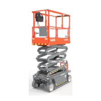
1-4. Major Assemblies
The aerial platform consists of three major assemblies.
The platform, lifting mechanism and the base. An
operator’s control box is mounted on the platform guard-
rail. Auxiliary and emergency controls are located at
the base.
1-5. Platform
The platform is constructed of a tubular support frame,
a skid-resistant “diamond plate” deck surface and 43-
1/2" (1100mm) Model 3015 or 41" (1042mm) Model 3219
and 41-1/2” to 43" (1050 - 1100mm) Models 32xx, 46xx,
4830 and 68xx high hinged guardrails with 6" (152mm)
toe boards and mid-rails. The platform can be entered
from the rear through an entry chain or optional spring-
returned gate with latch. The platform is also equipped
with an extension platform.
1-6. Operator’s Control Box
A removable control box, mounted at the front right of
the platform, contains controls for aerial platform mo-
tion and emergency stopping.
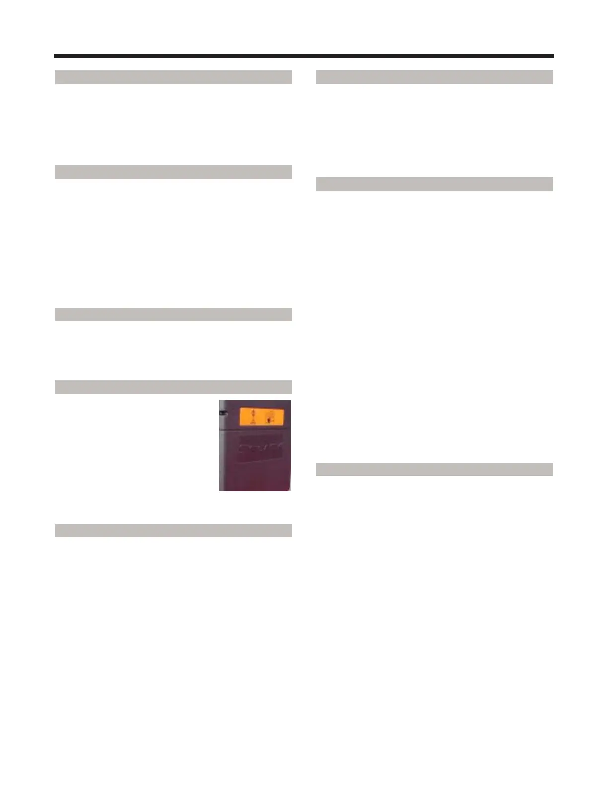
1-7. Manual Storage Box
This weather resistant box is mounted
at the front of the platform. It contains
the Operating Manual, the Operating/
Maintenance and Parts Manual and
other important documentation. The
Operating Manual for this make and
model of aerial platform MUST remain
with the aerial platform and should be
stored in this box.
1-8. Lifting Mechanism
The lifting mechanism is constructed of formed steel
or tube sections making up a scissor-type assembly.
The “scissors” assembly is raised and lowered by one
or more single-acting hydraulic lift cylinders with
holding valves. A two-section pump, driven by an
electric motor, provides hydraulic power to the lift
cylinders.
1-9. Maintenance Support/Safety Bar
A Maintenance Support, located inside the lifting mecha-
nism (when properly positioned) can support the scis-
sors and empty platform. The Maintenance Support
MUST be used during inspection and maintenance or
when repairs are being performed within the lifting
mechanism.
1-10. Base
The base is a rigid, one-piece weldment which sup-
ports two swing out trays.
• On Models 3015 and 3219: One tray contains
the hydraulic and electrical components. The other
tray contains the battery charger and four (4) 6
volt batteries. The front axle has two hydraulic
motor-driven wheels , steerable by a hydraulic
cylinder. The rear axle is fixed and has one or two
spring-applied hydraulically-released parking
brake.
• On Models 3220, 3226, 4620, 4626, 4830, 6826
and 6832: One tray contains the hydraulic and
electrical components. The other tray contains the
battery charger and four (4) 6 volt batteries. The
front axle has two non-driven wheels, steerable
by a hydraulic cylinder. The rear axle has two
hydraulic motor-driven wheels and one or two
spring-applied hydraulically-released parking
brakes.
1-11. Lowering Warning System (If Equipped)
• (If Equipped) - A lowering warning system
automatically stops the lowering function before
reaching the fully retracted position and sounds
an alarm.
 Loading...