12 / 16
Copyright (c) 2009-2013 RoboPeak Team
Copyright (c) 2013-2023 Shanghai Slamtec Co., Ltd.
RPLIDAR C1 Pin Definition and Specification
The RPLIDAR C1 uses separate 5V DC power for powering the range scanner
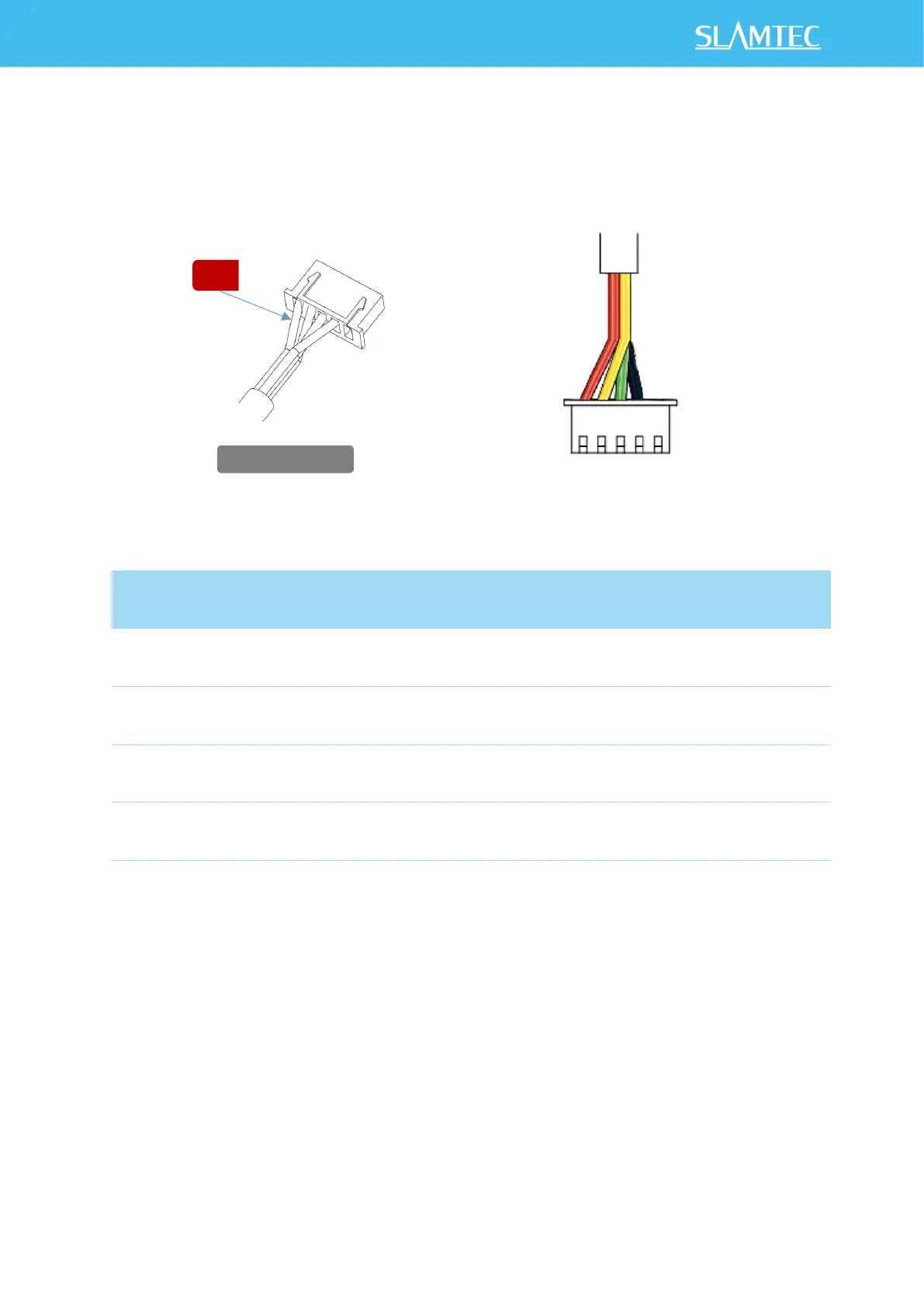
core and the motor system. And the standard RPLIDAR C1 uses XH2.54-5P male
socket. Detailed interface definition is shown in the following figure:
Figure 3-1 RPLIDAR C1 Pins
Figure 3-2 RPLIDAR C1 Pin Definition and Specification
With build-in and speed-adjustable motor driver, RPLIDAR C1 can control the
start, the stop and the rotating speed of the motor via the MOTOCTL signal.
o Reference Design for RPLIDAR development