SMA Solar Technology AG 3 Information on Off-Grid Systems and System Description
Installation - Quick Reference Guide Off-Grid-IS-en-30 15
3.4 Optional Devices and Functions
Use of the following devices is optional in an off-grid system:
Information on clusters
Device types within a cluster
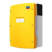
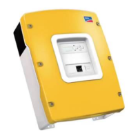
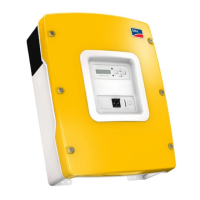
A cluster can consist of the following device types:
Device type Potential device types within a cluster Explanation
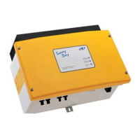
SI3.0M-11 SI3.0M-11 A cluster must consist of the same device types.
SI4.4M-11 SI4.4M-11
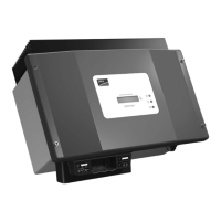
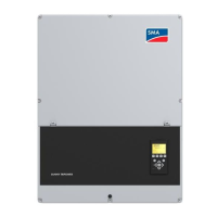
SI6.0H-11 SI6.0H-11 or SI8.0H-11 A cluster can consist of different device types.
If the device types within the cluster are different,
the master must be device type SI8.0H-11.
SI8.0H-11 SI6.0H-11 or SI8.0H-11
Clusters in single-phase single-cluster systems
In single-phase single-cluster systems, the Sunny Island inverters must be device type SI6.0H-11 and SI8.0H-11.
If the device types within the cluster are different, the master must be an SI8.0H-11.
Clusters in multicluster systems
In multicluster systems, the Sunny Island inverters must be device type SI6.0H-11 and SI8.0H-11. The clusters can
consist of different Sunny Island device types. If the device types within the cluster are different, the master must be
an SI8.0H-11.
Connecting the Sunny Island inverters in single-phase single-cluster systems
In a single-phase single cluster system, the following cable lengths and conductor cross-sections must be designed
the same way:
• From the generator to each Sunny Island
• From each Sunny Island to the AC distribution board
• From the BatFuse to each Sunny Island
The same design is a requirement for stable and symmetrical operation of the off-grid system.
Maximum PV system power
In off-grid systems, the maximum PV system power depends on the total power of the Sunny Island inverters.
• Maximum output power of the PV system per SI3.0M-11: 4,600 W
• Maximum output power of the PV system per SI4.4M-11: 4,600 W
• Maximum output power of the PV system per SI6.0H-11: 9,200 W
• Maximum output power of the PV system per SI8.0H-11: 12,000 W
The maximum output power of the PV system must be observed to ensure stable operation of the off-grid system.
Device Description
Load-shedding contactor Contactor controlled by the Sunny Island for isolation of loads
Sunny WebBox Remote monitoring and system configuration of the off-grid system
Sunny Island Charger 50 Charge controller for off-grid systems with lead-acid batteries
A maximum of four Sunny Island Charger charge controllers can be connected to a
cluster. In multicluster systems, four Sunny Island Charger charge controllers can be
connected to each cluster. If lithium-ion batteries are used, no charge controllers can
be connected.
 Loading...

