1
EFE 2500A /AF - 4000A/AS/AN
1.TABLE OF CONTENTS
1.TABLE OF CONTENTS ..................................................................................................................... 1
2.CONGRATULATIONS AND THANK YOU! ........................................................................................ 3
3.SYMBOLS IN MANUAL ................................................................................................................... 4
4.CONTACT DETAILS & HELP DESK .................................................................................................... 5
5.ELECTRICAL CONNECTION NOTICE ................................................................................................ 6
6. WARNINGS & SAFETY ................................................................................................................... 7
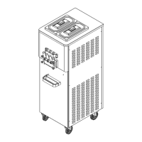
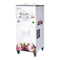
7. PARTS IDENTIFICATION ................................................................................................................ 9
7.1 Exploded View of Machine .................................................................................................... 9
7.1.1. EFE 2500 A/AF ................................................................................................................ 9
7.1.2 EFE 4000 A/AS ............................................................................................................... 11
7.1.3 EFE 4000 AN .................................................................................................................. 13
7.2 Exploded View of Dispensing Head ...................................................................................... 15
7.3 Exploded View of Self Service Unit ...................................................................................... 16
7.4 Exploded View of Air Tube ................................................................................................... 17
7.5 Exploded View of Liquid Level Sensor .................................................................................. 18
8. MACHINES WITH AIR-COOLED CONDENSER .............................................................................. 19
9. MACHINES WITH WATER-COOLED CONDENSER ........................................................................ 20
10. CONTROL DIAL .......................................................................................................................... 21
11. OPERATING PROCEDURE .......................................................................................................... 22
12. PREPARATION AND START UP PROCEDURE ............................................................................. 22
12.1 PREPARATION .................................................................................................................... 22
12.2 STARTING THE MACHINE ................................................................................................... 23
12.3 DISPENSING ICE CREAM ..................................................................................................... 24
13. STEP-BY-STEP CLEANING - SANITIZING PROCEDURE ................................................................ 24
13.1 CLEANING PROCEDURE ...................................................................................................... 25
13.2 BRUSH CLEANING PROCEDURE .......................................................................................... 27
13.3 SANITIZING PROCEDURE .................................................................................................... 29
14. STEP-BY-STEP ASSEMBLY PROCEDURE ..................................................................................... 30
14.1 DISPENSING HEAD ASSEMBLY ............................................................................................ 30
14.1.1 Dispensing Head O-Ring Assembly: ............................................................................ 30
14.1.2 Dispensing Head Piston – O-Ring Assembly: .............................................................. 30
14.1.3 Dispensing Head Piston Assembly: ............................................................................. 31
14.1.4 Dispensing Head Piston Lifter Assembly: .................................................................... 32
14.1.5 Dispensing Head Lifter Rod Assembly: ....................................................................... 33
14.1.6 Dispensing Head Assembled ....................................................................................... 33
14.2 BEATER ASSEMBLY ............................................................................................................. 34
14.2.1 Seal Assembly:............................................................................................................. 34
14.2.2 Inserting the Beater into the Barrel ............................................................................ 34