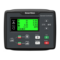
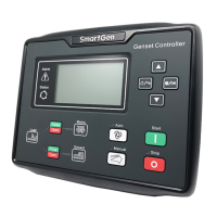
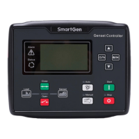
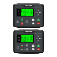
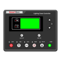
ALC700 Series Light Tower Set Controller
ALC700 Series Light Tower Set Controller 2018-03-02 Version 1.4 Page 31 of 51
Total output current: 8A
If 1~4 is all used, the maximum current of
each light is 2A.
RS485 communication ports
Communicate with PC.
Light tower set
A-phase voltage
sensing input
Connected to A-phase of light tower set
(2A fuse is recommended).
Light tower set
B-phase voltage
sensing input
Connected to B-phase of light tower set
(2A fuse is recommended).
Light tower set
C-phase voltage
sensing input
Connected to C-phase of light tower set
(2A fuse is recommended).
Light tower set
N-wire input
Connected to N-wire of light tower set.
Public terminal of sensor, connect to
enclosure or negative of starter battery.
Engine temperature sensor input.
Externally connected to resistor sensor.
Oil pressure sensor input. Externally
connected to resistor sensor.
Fuel level sensor input. Externally
connected to resistor sensor.
Flexible sensor input. Externally
connected to resistor sensor.
Connect to positive of magnetic pickup.
Connect to negative of magnetic pickup;
(B-) has already connected internal.
Digital input; connect B- is active.
Digital input; connect B- is active.
Digital input; connect B- is active.
Digital input; connect B- is active.
1# light control feedback input; connect
B- is active.
2# light control feedback input; connect
B- is active.
3# light control feedback input; connect
 Loading...