Do you have a question about the Smartgen HGM6510 and is the answer not in the manual?
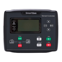
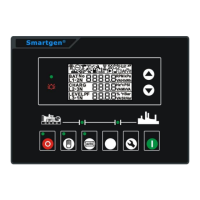
Visual layout of the Gen-Set Controller and indicator lights.
Details the two primary operational modes of the controller.
Lists measured electrical parameters for the generator and bus/mains.
Parameters related to synchronizing the generator with the bus.
Lists various generator abnormal conditions and fault display types.
Describes accurate measurement and display of electrical and engine parameters.
Outlines automatic operation, protection functions, and maintenance reminders.
Details communication interfaces, custom logic, and modular design.
Details voltage, current, frequency, and relay output ratings and specifications.
Covers communication interfaces, dimensions, and working conditions.
Describes the function of the various indicator LEDs on the panel.
Explains the function of each pushbutton and control element on the panel.
Details the sequence and process for automatic parallel operation start and stop.
Details the sequence and process for manual operation start and stop.
Lists alarms that warn but do not shut down the genset.
Lists alarms that cause immediate shutdown of the genset.
Lists alarms that trip the generator and stop operation.
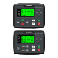
Details the general information and status screens displayed on the controller's LCD.
Shows detailed engine parameters such as speed, oil pressure, and temperature.
Displays generator electrical parameters and bus voltage/frequency data.
Shows synchronization status and lists active alarms with their types and descriptions.
Covers system event logging and controller information display on the LCD.
Guides users through setting and adjusting controller parameters via the interface.
Details the functions and types of configurable input ports (1-9).
Details the functions and types of configurable output ports (1-5).
Explains how the controller logs shutdown, warning, and trip events.
Shows the layout and terminal descriptions for the controller's back panel.
Describes the controller's interface capabilities with Engine Control Units (ECUs).
Provides step-by-step guides for debugging single unit and parallel operations.
Steps for performing manual parallel operation when the genset is off-load.
Steps for performing manual parallel operation when the genset is on-load.
Details the procedures for automatic parallel operation modes.
Lists common problems and their potential solutions for the controller.
Illustrates general and application-specific wiring connections for the controller.
Details the RS232 and RS485 communication protocols used by the controller.
Provides physical dimensions for installation and panel cutout.
| Crank Interrupt | Yes |
|---|---|
| Alternator Input | Yes |
| Current Input | Yes |
| Display | LCD |
| Input Voltage | 8-35VDC |
| Communication | RS485 |
| Programmable Relay Output | 5A/250VAC, 5A/30VDC |
| Operating Temp. | -25°C to +70°C |
| Communication Protocol | MODBUS protocol |