6.2 TESTS
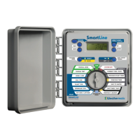
Your SmartLine
®
controller can assist you with several diagnos-
tic functions by pressing NEXT when TESTS appears.
6.2.1 OUTPUTS
Use ▲ arrow to select OUTPUTS function. Then use NEXT
and BACK buttons to scroll through MV and Zone Valves to
view AC Amp reading for each valve. Scroll back to OUT-
PUTS display to move to next diagnostic function. Typical
range is 150 to 350 mA per valve with a valve connected.
Current exceeding 350 mA per valve could be an indication
of a partial short. Current readings less than 30 mA will indi-
cate an open circuit. Note: If you have more than one valve
on a zone, the SmartLine
®
controller will measure total cur-
rent for the combined valves.
6.2.2 BATTERY
Use ▲ arrow button and Battery will flash. Use NEXT button
and you will see the DC V reading for the backup battery in
the
SmartLine
®
controller. A minimum of 7.5 volts is required
to power the processor and display. If the reading is less than
7.5 volts, the battery should be replaced. This function does
not provide voltage readings for the 9V battery in the optional
SLW weather station. However, if you turn the dial to any Auto
Adjust programming position, the battery icon reading you see
in the display is for the battery in the SLW weather station.
(The SL800 uses a Real Time Calendar Clock instead of a
backup battery to maintain correct time during a power out-
age. A battery icon will not be seen in the display unless you
turn the dial to any Auto Adjust position to the check the bat-
tery in the optional SLW.)
6.2.3 24V PWR
This function displays output voltage at the transformer.
Normal reading is 24 to 30 volts AC.
6.2.4 LOCATOR
This feature will create a
“chatter” for a selected
valve as a convenient
method of locating buried
valves. Use NEXT and
BACK buttons to scroll to the
valve you want to “chatter.”
6.3 REVIEW
6.3.1 NEXT RUN
NEXT RUN is the total amount of run time Auto Adjust has
calculated for each zone for the next watering day based on
the deficit numbers and is available for review when you are