- 27 -
Example of step data input (1)
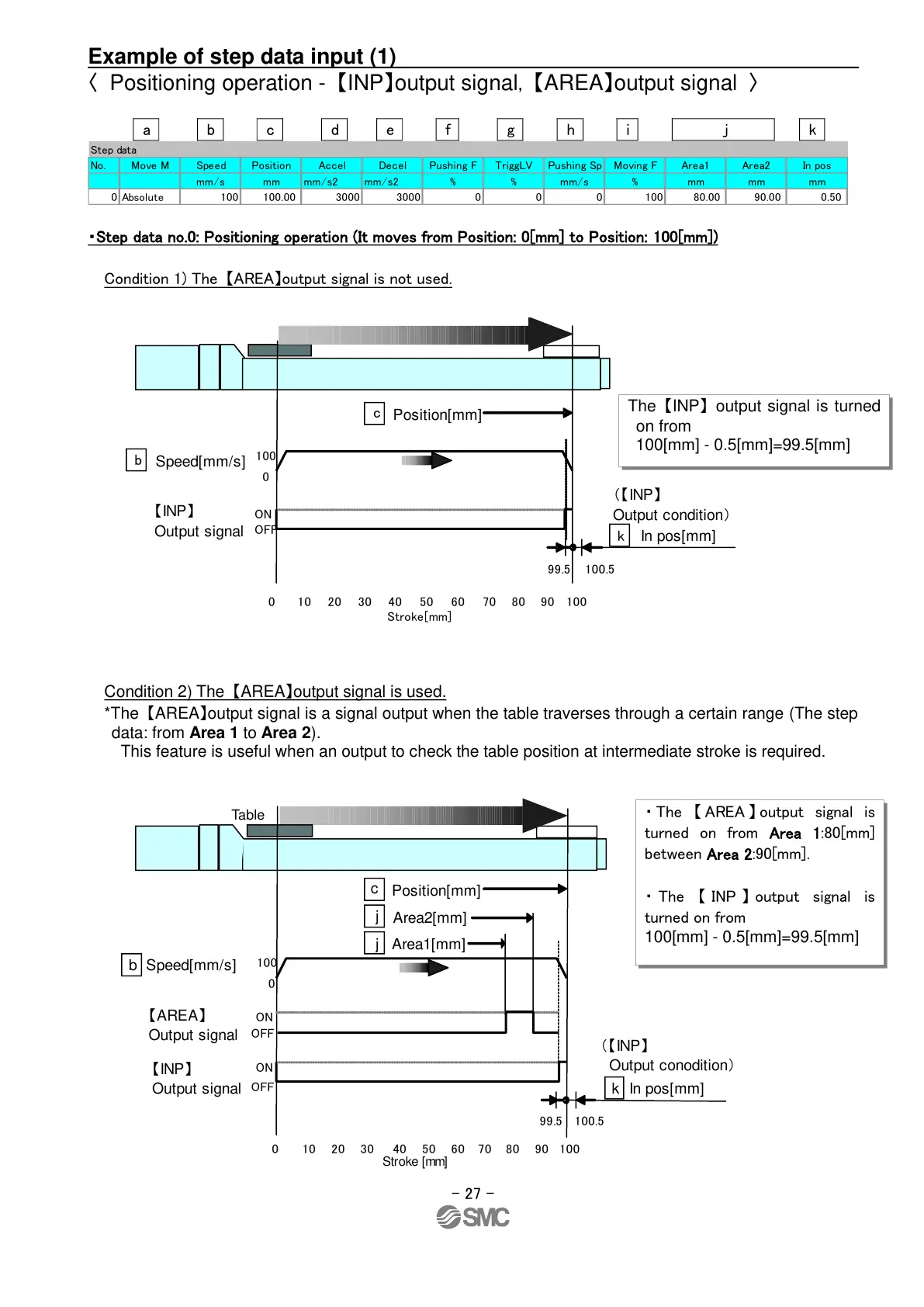
〈 Positioning operation - 【INP】output signal, 【AREA】output signal 〉
a b c d e f g h i j k
・Step data no.0: Positioning operation (It moves from Position: 0[mm] to Position: 100[mm])
Condition 1) The 【AREA】output signal is not used.
Condition 2) The 【AREA】output signal is used.
*The 【AREA】output signal is a signal output when the table traverses through a certain range (The step
data: from Area 1 to Area 2).
This feature is useful when an output to check the table position at intermediate stroke is required.
Step data
No. Move M Speed Position Accel Decel Pushing F TriggLV Pushing Sp Moving F Area1 Area2 In pos
mm/s mm mm/s2 mm/s2 % % mm/s % mm mm mm
0 Absolute 100 100.00 3000 3000 0 0 0 100 80.00 90.00 0.50
The 【INP】 output signal is turned
on from
100[mm] - 0.5[mm]=99.5[mm]
(【INP】
Output conodition)
・ The 【 AREA 】 output signal is
turned on from Area 1:80[mm]
between Area 2:90[mm].
・ The 【 INP 】 output signal is
turned on from
100[mm] - 0.5[mm]=99.5[mm]
2021-05-2010:32
DW913599

 Loading...


