-9-
No.EX##-OMP0013-A
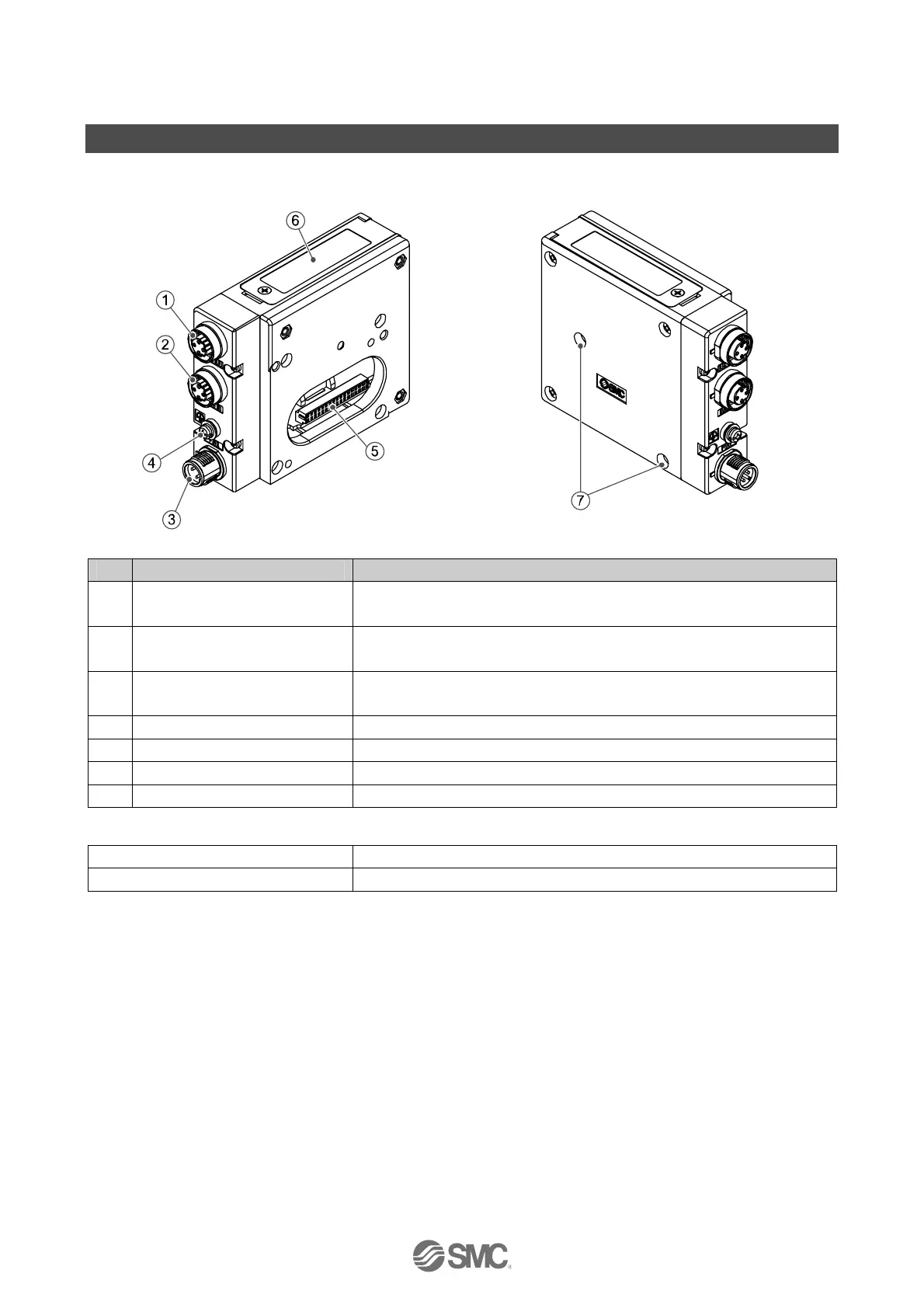
Summary of Product elements
<EX260-SEN1/-SEN2/-SEN3/-SEN4>
No. Element Description
1
Fieldbus interface connector
(BUS OUT)
EtherNet/IP
TM
connection PORT 2.
∗
1
(M12 4-pin socket, D-coded)
2
Fieldbus interface connector
(BUS IN)
EtherNet/IP
TM
connection PORT 1.
∗
1
(M12 4-pin socket, D-coded)
3 Power supply connector
Power supply with load voltage for valves and operating voltage for SI unit.
∗
1
(M12 4-pin plug, A-coded)
4 Ground terminal Functional earth. (M3 screw)
5 Output connector Output signal interface for valve manifold.
6 LED display LED display to indicate the status of the SI unit.
∗
2
7 Mounting hole Mounting hole for connection to the valve manifold.
Accessories
Hexagon socket head cap screw 2 pcs. M3 x 30 screw for connection to the valve manifold.
Seal cap 1 pc. seal cap for unused fieldbus interface connector (BUS OUT).
∗1: For details of suitable cables refer to the Accessories section on page 35
∗2: Refer to page 14 for the LED Indication and Settings.
 Loading...