-11-
No.EX##-OMP0013-A
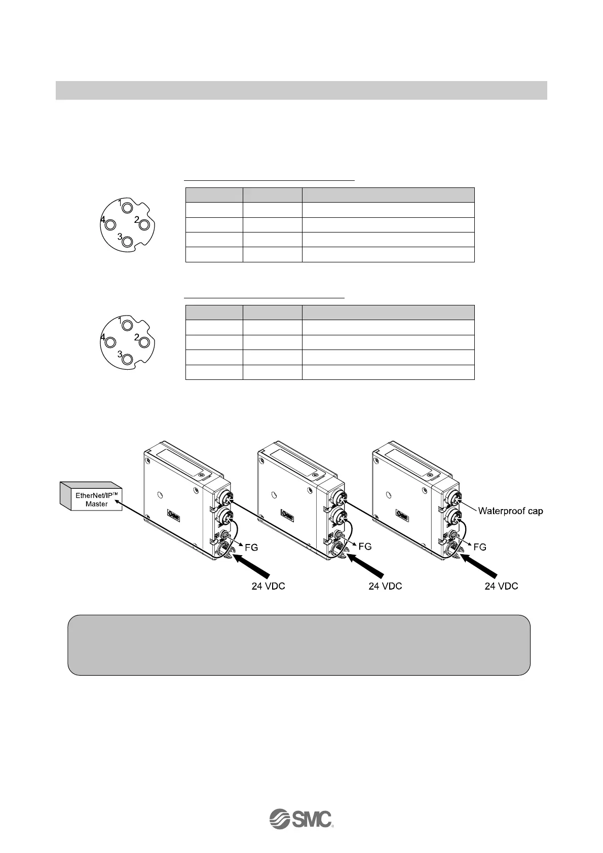
■Wiring
Select the appropriate cables to mate with the connectors mounted on the SI unit.
○Fieldbus interface connector layout
BUS OUT: M12 4-pin socket, D-coded
No. Designation Description
1 TD+ Transmit Data +
2 RD+ Receive Data +
3 TD
-
Transmit Data
-
4 RD
-
Receive Data
-
BUS IN: M12 4-pin socket, D-coded
No. Designation Description
1 TD+ Transmit Data +
2 RD+ Receive Data +
3 TD
-
Transmit Data
-
4 RD
-
Receive Data
-
Connect the "BUS IN" connector to the upstream device (PLC etc.) and connect the "BUS OUT" connector
to the downstream device.
Note
•Be sure to fit a seal cap on any unused connectors.
Proper use of the seal cap enables the enclosure to achieve IP67 specification.
∗: Refer to page 35 for the seal cap.
 Loading...