Implement diagnostic bits in the process data.
Supports the IO-Link communication protocol
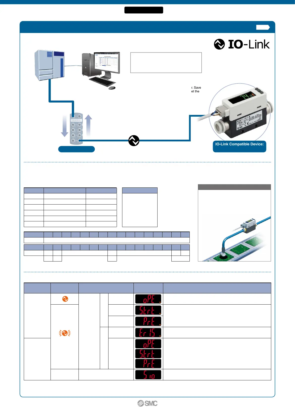
IO-Link is an open communication
interface technology between the sensor/
actuator and the I/O terminal that is an
international standard: IEC61131-9.
IO-Link Master
Device settings
can be set by the
master.
• Threshold value
• Operation
mode, etc.
Read the device data.
• Switch ON/OFF signal and analog value
•
Device information:
Manufacturer, Product part number, Serial number, etc.
• Normal or abnormal device status
• Cable breakage
Application Example
Configuration File (IODD File
*
1
)
· Manufacturer · Product part no.
· Set value
*1 IODD File:
IODD is an abbreviation of IO Device
Description. This file is necessary for setting
the device and connecting it to a master. Save
the IODD file on the PC to be used to set the
device prior to use.
For the predictive maintenance of
suction verification
The flow rate “switch ON/OFF signals” and
“analog values” are monitored to determine
the suction status. The process and
suction status can then
be compared.
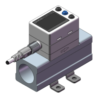
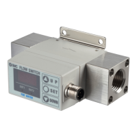
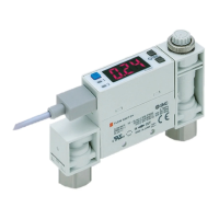
IO-Link Compatible Device:
Digital Flow Switch
Operation and Display
Communication
with master
IO-Link status
indicator light
Status
Screen display
*
2
Description
Ye s
*
1
IO-Link
mode
Normal
Operate Normal communication status (readout of measured value)
*
1
(Flashing)
Start up
At the start of communication
Preoperate
Abnormal
Version does
not match
The IO-Link version does not match that of the master.
The master uses version 1.0.
No
Communication
disconnection
Normal communication was not received for 1 s or longer.
OFF SIO mode
General switch output
*1 In IO-Link mode, the IO-Link indicator is ON or flashing.
*2 “LoC” is displayed when the data storage lock is enabled. (Except for when the version does not match or when in SIO mode)
The display color can be set to red or green.
Diagnosis items
· Over current error
· Outside of rated flow
range
· Accumulated flow
error
· Internal product
malfunction
Process Data
Bit offset Item Note
0 OUT1 output 0: OFF 1: ON
1 OUT2 output 0: OFF 1: ON
8 Diagnosis (flow rate) 0: OFF 1: ON
14 Fixed output 0: OFF 1: ON
15 Diagnosis (error) 0: OFF 1: ON
16 to 31 Measured flow rate value Signed 16 bit
Bit offset 31 30 29 28 27 26 25 24 23 22 21 20 19 18 17 16
Item Measured flow rate value (PD)
Bit offset 15 14 13 12 11 10 9 8 7 6 5 4 3 2 1 0
Item
Error Fixed
Reservation
Flow rate
Reservation
OUT2 OUT1
Diagnosis
Output
Diagnosis
Switch output
The diagnostic bit in the cyclic process data makes it easy to find problems with the equipment.
It is possible to find problems with the equipment in real time using the cyclic (periodic) data and to monitor such problems in detail with the noncyclic (aperiodic) data.
p. 10
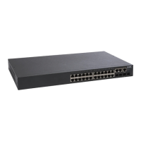
Fieldbus
PLC
PC
IO-Link Compatible PF2M7mm-m-Lm-mmm
4
2-Color Display
Digital Flow Switch PF2M7(-L) Series
 Loading...