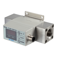
Series PFA/PFW
Specific Product Precautions 1
Be sure to read before handling.
Refer to page 27 for safety instructions.
1. Use with the specified voltage.
Use with voltage outside of the specifications can cause malfunc-
tion or switch damage, as well as electrocution and fire hazard, etc.
2. Never use a load which exceeds the maxi-
mum load capacity.
This can cause damage to switches.
3. Do not use loads which generate surge volt-
age.
The switch's output section is provided with a surge protection
feature in its circuit, but repeated application can cause damage.
When directly driving surge generating loads, such as relays and
solenoid valves, etc., use a type of switch which has a built-in
surge absorbing element.
4. Since the fluids which can be used differ
depending on the product, be certain to con-
firm the specifications.
Since switches do not have explosion proof construction, do not
use flammable gases or fluids. This may cause fire or explosion.
5. Take note of the switch's internal voltage
drop.
When operated below the prescribed voltage, the load may not
operate, even if the switch operates normally. Confirm the load's
operating voltage and see that the following formula is satisfied.
[When used for air]
6. Be certain to observe specifications for the
measured flow rate and operating pressure.
Operation at a flow rate exceeding the prescribed range can cause
damage.
In addition, the switch will be damaged if operated above the max-
imum operating pressure.
[When used for water]
7. Be certain to observe specifications for the
measured flow rate and operating pressure.
Operation at a flow rate exceeding the prescribed range can cause
damage.
In addition, the switch will be damaged if operated above the max-
imum operating pressure. In particular, avoid application of pres-
sure above the specifications caused by water hammer.
<Pressure Reduction Measure Examples>
a) Use a water hammer relief valve, etc., to slow the valve's closing
speed.
b) Absorb impact pressure by using an accumulator, or elastic piping
material such as rubber hose.
c) Make the length of piping as short as possible.
8. Design so that the flow of liquid always fills
the detection passage.
Especially in the case of vertical mounting, set up so that flow
moves from the bottom to the top.
9. Operate at a flow rate within the flow rate
measurement range.
If operated outside of the flow rate measurement range, the
Karman vortex will not be generated and normal measurement will
become impossible.
Design and Selection Design and Selection
28
1. The switch's data will not be cleared even if
the power is turned off.
Since the input data is held in an EEPROM, it will not be cleared
even if the power is turned off. (Rewriting is possible up to 10⁵
times, and the data holding time is 20 years.)
Mounting
1. Mount switches using the proper tightening
torque.
The switch may be damaged if it is tightened above the tightening
torque range. Also, if it is tightened below the tightening torque
range, the connecting thread section may become loose.
2. When connecting piping to the switch, do
this by applying a wrench to the metal part
which is integrated with the piping section.
Never apply a wrench to the portion which is made of resin, as this
can cause damage to the switch.
3. Pay attention to the fluid flow direction.
Install and connect piping so that fluid flows in the direction of the
arrow indicated on the body.
4. Before connecting piping to the switch,
remove dirt, etc., from inside the piping by
blowing it out with air.
5. Do not drop or bump.
Do not drop, bump or apply excessive impacts (490m/s²) while
handling. Although the body of the switch may not be damaged, the
inside of the switch could be damaged and cause a malfunction.
6. Hold the product by the body when handling.
Since the tensile strength of the power cord is 49N, pulling it with
a force greater than this can cause damage. Hold by the body
when handling.
7. Use after confirming that equipment is oper-
ating properly.
After a new installation, system repair or renovation, connect the
fluid and power, etc., and then perform appropriate function and
leak tests to confirm that mounting has been done correctly.
8. Avoid mounting so that the bracket is on top.
The switch can be mounted vertically, horizontally or in any other
orientation, but avoid mounting with the bracket on top.
[When used for air]
9. Never mount a switch in a place that will be
used as a scaffold during piping work.
Damage may occur if subjected to an excessive load.
 Loading...