C
HAPTER
1
| Introduction
Overview
– 26 –
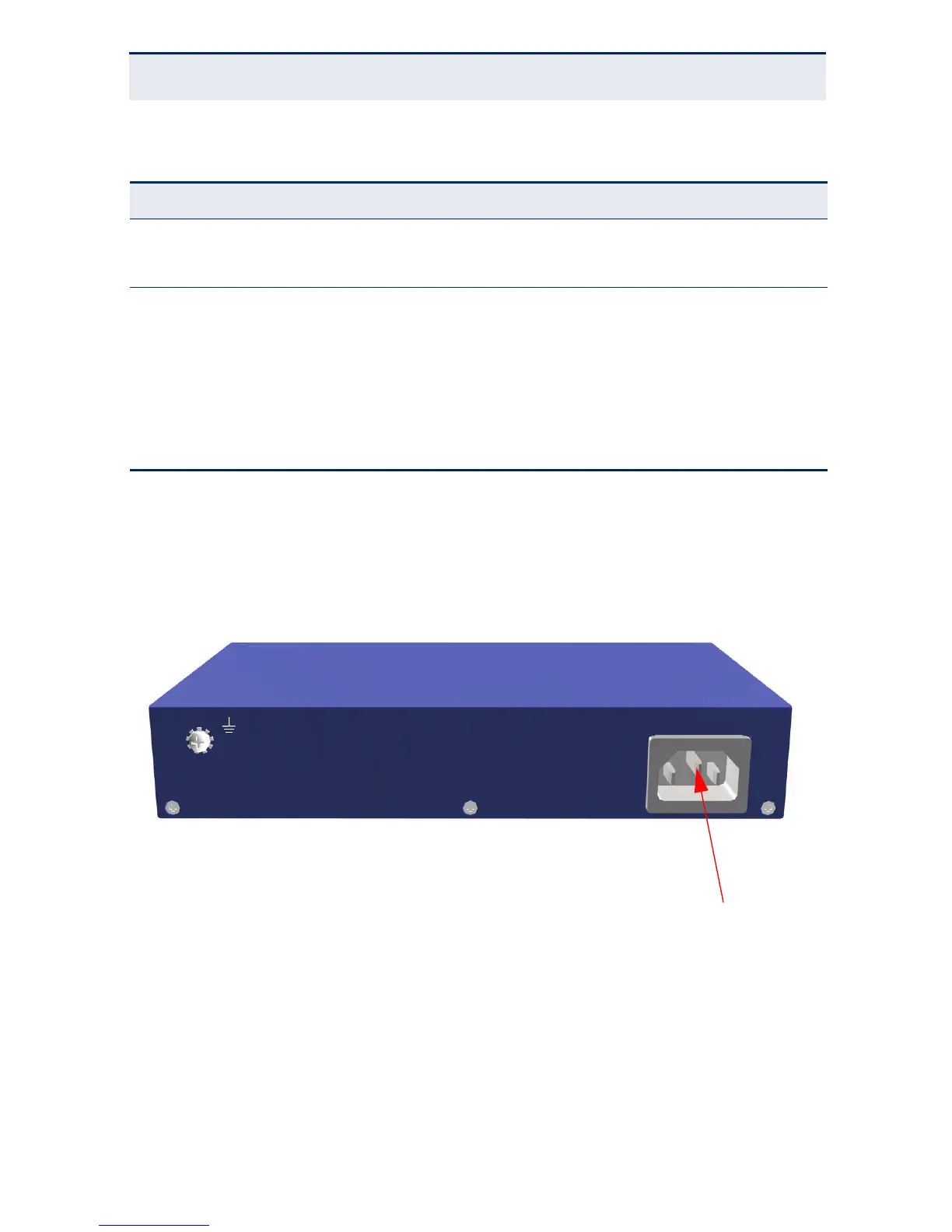
POWER SUPPLY INLET
There is one power inlet on the rear panel of the switch. The standard power
inlet is for the AC power cord.
Figure 4: Power Supply Inlet
GROUNDING POINT
To prevent accidental electrical shock or damage to your switch, it is
recommended that you ground the switch to an earth point by attaching a
grounding wire (not supplied) to the grounding point located on the rear panel,
with a metal screw. If located in a tall building, grounding points include metal
drain pipes, and other electrostatic conductive devices that lead to the ground,
or if located on the first floor of a building, the ground outside itself.
Table 3: System Status LEDs
LED Condition Status
Power On Green The unit’s internal power supply is operating normally.
Off The unit has no power connected.
Diag On Green The system diagnostic test has completed successfully.
Flashing
Green
The system boot up is in progress.
On Amber /
Flashing
Amber
The system diagnostic test is in progress.
Off The system diagnostic has completed.
115-240Vac, 50-60Hz, 0.5A
 Loading...