82
Accessories
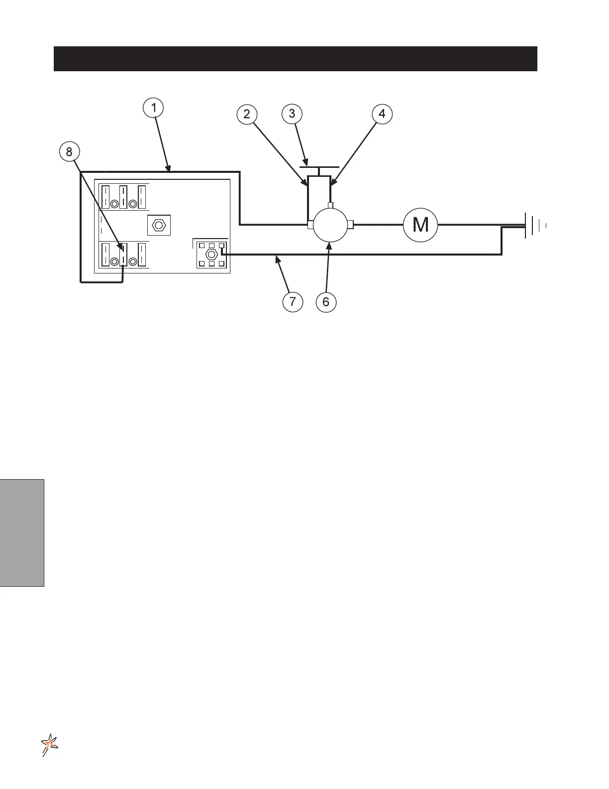
ELECTRIC HOSE REEL WIRING DIAGRAM
REF# PART# DESCRIPTION QUANTITY
8843-132 Flexguard
3
/
8
ID 1
1 8919-144 10GA Red Wire 144" 1
8901 Slide-On Connector 1
2 16-979 Wire, Switch to Solenoid Hot Terminal 1
3 33-251 Push Button Switch 1
4 16-978 Wire, Switch to Solenoid Start Terminal 1
6 13-750 Solenoid 1
SOLENOID TERMINALS
HN -516-24
5
/
16
- 24 Hex Nut 2
HN -10-32 10 - 32 Hex Nut 1
7 8931-144 10GA White Wire 144" 1
8901 Slide-On Connector 1
8 33-273 Auto Blade Type Fuse 30Amp 1
CONNECTION INSTRUCTIONS
Route wire harness along side of tank and over to fuse block taking care to stay clear of moving parts or hot
3
/
8
". Place one 8963 heat shrink (
1
/
4
x 1
1
/
4
) on each
wire before crimping 8901 slide on connectors to the red and white wires. Connect the two wires to the fuse
amp) into fuse block.
Make certain you are connecting positive (+) to positive; negative (-) to negative while
attaching power leads. If you do not observe polarity, damage will result to electrical compo-
nents.
Use Dielectric Grease On All Electrical Connections