Do you have a question about the Smithco Spray Star 2000 and is the answer not in the manual?
Guidance on using dielectric grease for all electrical connections.
Instructions for cleaning or replacing the engine air cleaner element.
Guidance on changing engine oil based on air temperature and service intervals.
Information on correct tire pressure for safe operation and tire longevity.
Step-by-step instructions for safely mounting and torquing wheels.
Safety precautions and procedures for battery maintenance and jump-starting.
Procedure for storing the machine for two or more months to ensure proper preservation.
Procedure to diagnose and correct 'wheel creep' when the engine is running.
Instructions for checking and adjusting the spray pump belt tension.
Explanation of the foot switch function for controlling booms.
How to engage and disengage the ground speed control foot switch.
Operation of the spray boss control lever for speed adjustment.
Location and operation of the tank agitation valve.
Daily and weekly maintenance checks for the machine.
Section for recording specific inspection details and findings.
Initial maintenance tasks to be performed after the first 8 hours of operation.
Daily pre-operation checks and maintenance procedures.
Maintenance tasks required after the first 50 hours of operation.
Maintenance tasks to be performed every 100 operating hours.
Maintenance tasks to be performed every 200 operating hours.
Periodic maintenance tasks for every 500 hours or annually.
Maintenance tasks to be performed every 800 operating hours.
Maintenance tasks to be performed every 1500 operating hours.
Maintenance tasks to be performed every 3000 operating hours.
Maintenance tasks to be performed every two years.
Key to understanding the color codes used in the wiring diagram.
Specifications for the hydrostatic pump, including displacement and pressure ratings.
Specifications for the gear pump, including displacement and flow rate.
Instructions for mounting the boom assembly to the truck frame.
Diagram and specifications for the water meter kit in liters.
Operational checks and procedures for adjusting the hose reel locking mechanism.
Step-by-step guide for replacing the hose on the reel.
Wiring diagram specific to the foam marker system.
Steps for mounting the front-mounted fresh water wash tank.
Steps for mounting the rear-mounted fresh water wash tank.
Procedure for safely starting the chemical clean-load system.
Instructions for loading chemicals into the hopper.
Procedure for loading chemicals using the suction lance.
Steps for safely shutting down the chemical clean-load system.
List of replacement filters for the machine.
List of replacement belts for the machine.
List of available seal kits for various components.
Recommended engine oil and hydraulic fluid types.
List of miscellaneous other parts for the machine.
Specifies the duration of the product warranty.
Details the responsibilities of the product owner for maintenance and training.
Guidance on how to get warranty service and contact information.
Warranty coverage for parts scheduled for maintenance replacement.
List of failures and conditions explicitly excluded from warranty coverage.
| Brand | Smithco |
|---|---|
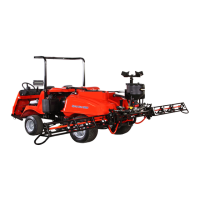
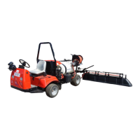
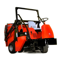
| Model | Spray Star 2000 |
| Category | Paint Sprayer |
| Language | English |