82
Accessories
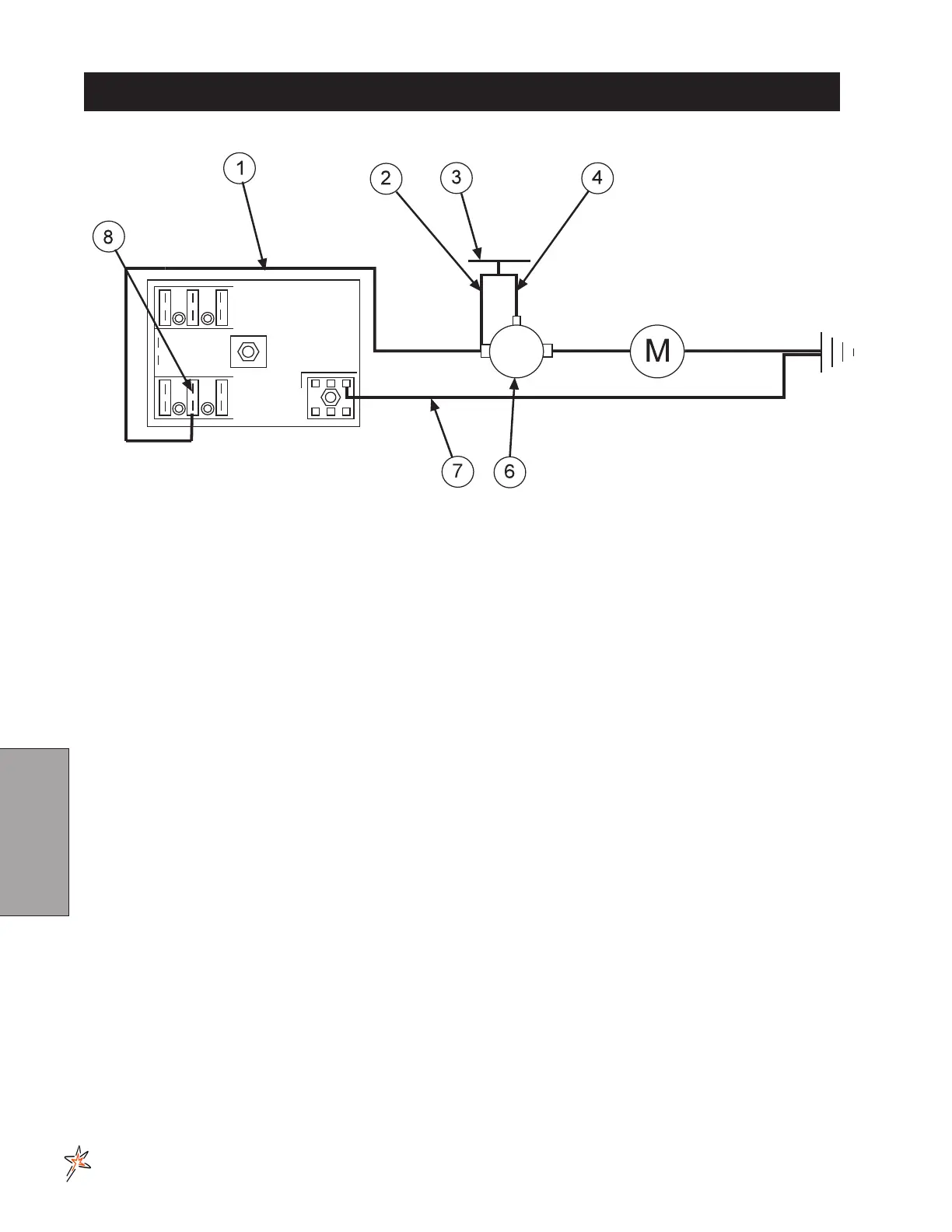
ELECTRIC HOSE REEL WIRING DIAGRAM
REF# PART# DESCRIPTION QUANTITY
8843-132 Flexguard
3
/
8
ID 1
1 8919-144 10GA Red Wire 144" 1
8901 Slide-On Connector 1
2 16-979 Wire, Switch to Solenoid Hot Terminal 1
3 33-251 Push Button Switch 1
4 16-978 Wire, Switch to Solenoid Start Terminal 1
6 13-750 Solenoid 1
SOLENOID TERMINALS
HN -516-24
5
/
16
- 24 Hex Nut 2
HN -10-32 10 - 32 Hex Nut 1
7 8931-144 10GA White Wire 144" 1
8901 Slide-On Connector 1
8 33-273 Auto Blade Type Fuse 30Amp 1
CONNECTION INSTRUCTIONS
Route wire harness along side of tank and over to fuse block taking care to stay clear of moving parts or hot
engine components. Cut o excess wire and strip back
3
/
8
". Place one 8963 heat shrink (
1
/
4
x 1
1
/
4
) on each
wire before crimping 8901 slide on connectors to the red and white wires. Connect the two wires to the fuse
block rst the red to the (+) positive and the white to the (-) negative. Put the 33-273 auto blade type fuse (30
amp) into fuse block.
Make certain you are connecting positive (+) to positive; negative (-) to negative while
attaching power leads. If you do not observe polarity, damage will result to electrical compo-
nents.
Use Dielectric Grease On All Electrical Connections