8
ASSEMBLING THE UNIT cont'd
be welded, following the instructions given in the service
functions (PROCESS PARAMS) paragraph. Remove the
gas nozzle and unscrew the contact tip of the torch. Press
the torch button until the wire comes out. BE CAREFUL
to keep your face away from the end lance while the
wire is coming out, screw on the contact tip and t the
gas nozzle.
Open the canister adapter and adjust the gas ow as
follows: 25-30CFH(12–14 l/min) steels, 40CFH (19 l/min)
aluminum.
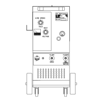
During welding, the display screen
A
displays the actual
work current and voltage. The displayed values may be
slightly different to those set. This can depend on numerous
different factors - type of torch, thickness different to
nominal thickness, distance between current nozzle and
the material being welded, and the welding speed. After
welding, the current and voltage values remain stored on
the display
A
. To display the set values, the handle
B
will have to be moved slightly, while, by pushing the torch
button without welding, the display screen
A
shows the
empty voltage value and a current value of 0.
How to install wire through the MIG225PP Push-
Pull Torch found in MIG225PP Owner's Manual form
WC6226.
When the machine is switched
on, for a few moments the
display screen
A
displays:
the article number of the
machine, the version and
development date of the
software, and the release number of the synergic curves (this
information is also given in Section 7.1 SERVICE FUNCTIONS).
Immediately after switch-on, the display screen
A
shows:
The synergic curve used, the welding mode 2T, 4T or
3L, SPOT function, if active, the letters PP if a push-pull
welding torch is used, the welding process "SHORT or
PULSED"(optional), the welding current, the speed of
the welding wire in inches/min, the welding voltage and
the recommended thickness. To increase or decrease the
welding parameters, simply adjust by means of knob
B
.
The values all change together in a synergic way.
To change the welding voltage
V
, simply press the knob
B
for less than 2 seconds. The display screen will show
(Arc Length) an adjustment bar with central 0. The value
can be changed by means of the knob
B
from -9.9 to
9.9. To exit from the function, briey press the knob
B
.
By changing the value, once having exited the sub-menu,
alongside the voltage
V
, an arrow will appear turned
upwards to indicate a higher adjustment of the set value,
while the arrow turned downwards will indicate a lower
adjustment.
QUICK START GUIDE
 Loading...