S - LED
Slope up. This is the time in which the
cur
rent, starting from the minimum,
reaches
the
set current value. (0-10 sec.)
Slope Up can be used to assist in preheating cold material
prior to depositing filler material, or to ensure a soft start on
higher amperage settings.
T - LED
Main welding current. (10-130A in MMA
and
5-
150A in TIG)
V - LED
Second level of welding or base current. This
curr
ent
is always a percentage of the main.
Pulsed 2-stage or Pulsed 4-stage only - Use the
Second level of welding or base current to set
the low current pulse of the weld amperage,
which cools the weld puddle and affects overall
heat input. This current is always a percentage
of main current.
U - LED
Pulse frequency (0.16-250 Hz) The peak and
base times are equal. These pulses and the
base current level -V- between them (called the
Second level of welding ) alternately heat and
cool the molten weld puddle. The combined
effect gives better control of penetration, bead
width, undercutting, and heat input
W - LED
Slope down. This is the time in which the
cur-
rent reaches the minimum value and the
ar
c.
Slope Down should be used while
welding materials that are crack sensitive,
and/or to eliminate the crater at the end
of the weld.
X - LED
Post gas. Adjusts the time gas flows after
welding
ends. (0-30 sec.) Post Gas is required to cool the
tungsten rod and weld puddle, and to prevent
contamination of tungsten and weld. Increase post gas
time if tungsten or welds have a dark appearance.
Note: only those LEDs that refer to the chosen
welding
mode will light; i.e., in continuous TIG welding the LED
U
,
representing the pulse frequency, will not
light.
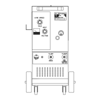
Each LED indicates the parameter that may be adjusted
by
means of the knob
AA
while the
LED
itself is lit.
Five
seconds
after the last variation, the LED involved will shut off;
the
main welding current will be displayed, and the
correspon
ding LED T
lights.
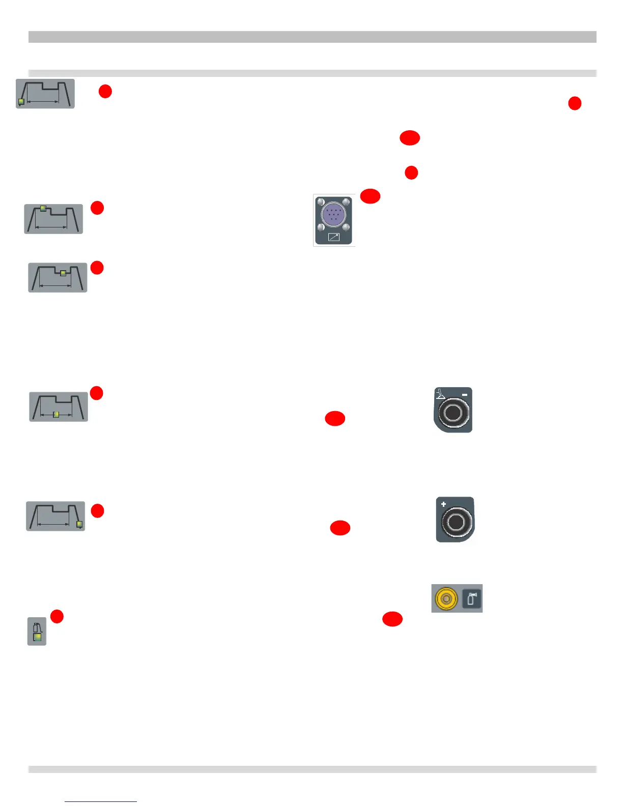
AE - 10-PIN CONNECTOR
The
following remote controls
are
connected to
this
connector:
a)
foot
contr
ol or on/off button.
b) torch with start
button.
c) torch with variable amperage device.
General Notes
Make sure the
insula
tion of the cables, electrode clamps,
sockets and plugs are intact, and that the size and length of
the welding cables are compatible with the current used.
AB - Negative output terminal
Plug the TIG torch in here.
AC -Positive output terminal (+).
Plug the “ground” cable in here.
AD - 1/4 GAS OUTLET FITTING
 Loading...