14 snapperpro.com
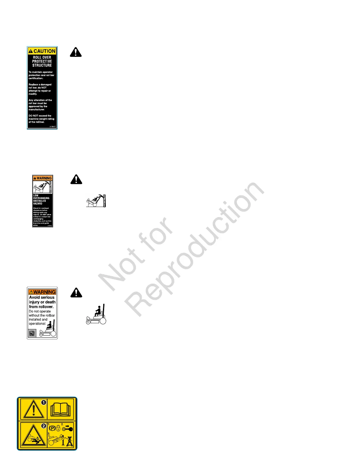
Decal, Caution, Folding Roll Bar
Part Number: 5104083YP
WARNING
Roll Over Protective Structure.
To maintain operator protection and roll
bar certification:
• Replace a damaged roll bar, do not
attempt to repair or modify.
• Any alteration of the roll bar must be
approved by the manufacturer.
• Do not exceed the machine weight
rating of the roll bar.
Decal, Warning, Roll Bar and Overhead
Obstacles
Part Number: 5100405YP
WARNING
Low overhanging
obstacles hazard.
• Check for overhead clearances
before driving under any objects.
Do not allow roll bar to contact low
overhanging obstacles, such as tree
branches and guide wires.
Decal, Warning, Roll Bar Removed
Part Number: 84008199
WARNING
Avoid serious
injury or death
from rollover.
• Do not operate without the roll bar
installed and operational.
Safety Icons for Optional Jack Kit
Accessory
An optional jack kit is available as an accessory through your
normal parts source. Please see the explanations below for
the safety icons displayed on the jack kit.
Part Number:5105632 - Decal, Warnings, Svc Jack
1.) Warning - Read the Operator's Manual.
2.) Crushing Hazard, Mower:(1.) Park machine on flat
level ground and engage the parking brake; (2.) Stop the
engine and remove the ignition key; (3.) Properly jack the
machine and secure with jack stands before working under
the machine.
Safety Interlock System
This unit is equipped with safety interlock switches. These
safety systems are present for your safety, do not attempt
to bypass safety switches, and never tamper with safety
devices. Check their operation regularly.
Operational SAFETY Checks
Test 1 - Engine SHOULD NOT crank if:
• PTO switch is engaged, OR
• Parking brake is not engaged.
Test 2 - Engine SHOULD crank if:
• PTO switch is not engaged, AND
• Parking brake is engaged.
Test 3 - Engine should SHUT OFF if:
• Operator rises off seat with PTO engaged, OR
• Operator rises off seat with parking brake disengaged.
Test 4 - Blade Brake Check
The mower blades and mower drive belt should come to a
complete stop within seven (7) seconds after electric PTO
switch is turned off (or operator rises off seat).If the unit fails
the blade brake check, it is advised not to use the unit until it
is repaired and passes the blade brake check.
Note:Once the engine has stopped, PTO switch must be
turned off, parking brake must be engaged, and the ground
speed control levers must be locked in the NEUTRAL position
after the operator returns to the seat in order to start the
engine.
Features and Controls
Control Functions and Locations
The information below briefly describes the function of
individual controls. Starting, stopping, driving, and mowing
require the combined use of several controls applied in
specific sequences. To learn what combination and sequence
of controls to use for various tasks see the Operation section.