40 snapperpro.com
2. Set the mower deck in the 3-1/2” (8,9 cm) cutting height
position.
3. Visually inspect the front deck lift levers (C):
• if the front flat edge of the deck lift lever is vertical,
the deck lift pedal linkage is adjusted correctly.
• if the front flat edge of the deck lift lever is not
vertical, the deck lift pedal linkage needs to be
adjusted.
4. Place blocking underneath the mower deck to support the
mower deck.
5. Loosen the jam nut (D) against the front ball joint (E).
6. Remove the 1/2" hardware and spacer (F) that secures
the deck lift linkage to the deck lift shaft. The deck lift
shaft is under tension by the deck lift assist springs and
it may be necessary to use a bar to position the deck lift
shaft so the tension is minimized and the 1/2" hardware
and spacer can be removed.
7. Turn the ball joint to lengthen or shorten the deck lift
pedal linkage so that it positions the front flat edge of the
deck lift lever vertically.
8. Re-install the deck lift pedal linkage to the deck lift shaft
and secure using the 1/2" hardware and spacer that was
previously removed.
9. Re-tighten the jam nut.
Deck Lift Rod Timing Adjustment (61"
Mower Decks)
1. Park the machine on a flat, level surface. Disengage the
PTO, engage the parking brake, turn off the engine, and
remove the ignition key. Verify that the tires are properly
inflated.
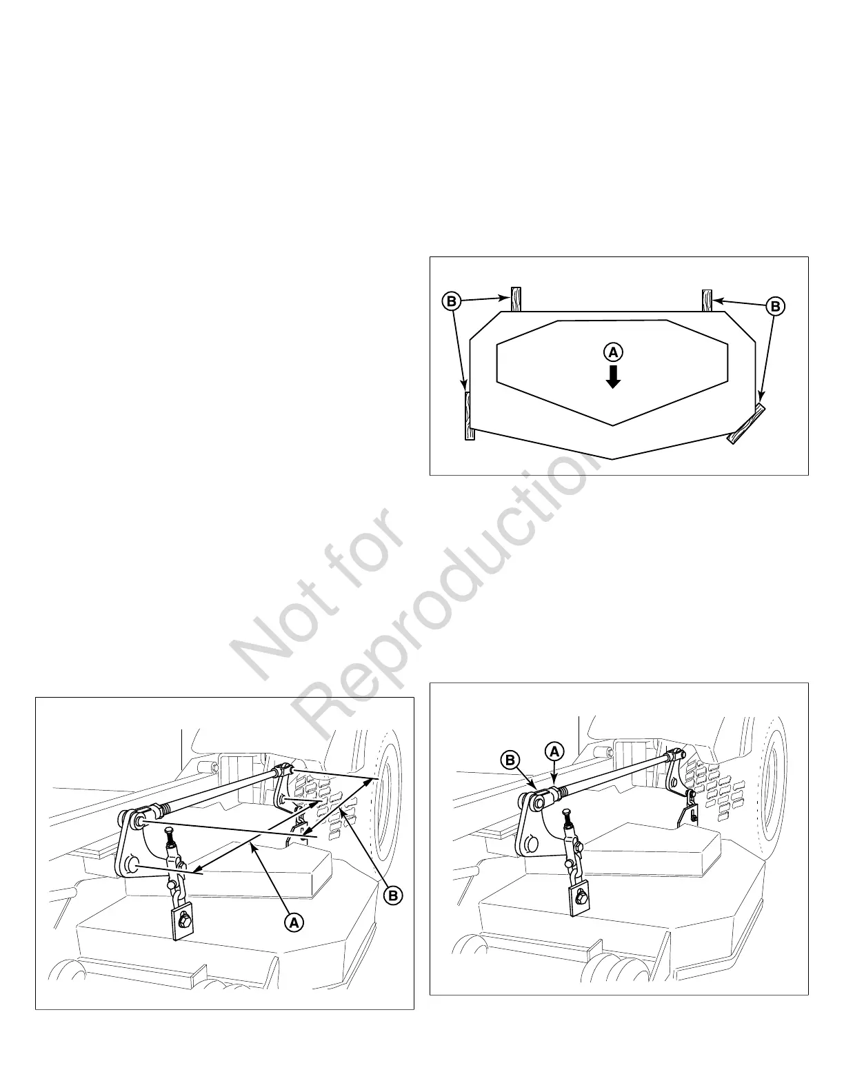
2. To check the lift rod timing, measure and record the
distance between the lift pivots (A, Figure 57) and the rod
pivots (B). Repeat for other side of unit.
57
3. If the measurements for the rods are equal, no further
adjustment is required. If the measurements are
NOT equal (greater than 1/8” (3,17 mm) difference),
adjustment is required continue with Step 4.
4. Lock the deck lift pedal in the TRANSPORT position.
Remove the cutting height adjustment pin and lower the
mower deck.
5. To ensure that the deck is in the lowest position, push the
pedal by hand towards the rear of the unit and install the
height adjustment pin in the 3” (7,6 cm) position to hold in
place.
6. Block up the mower deck until all hanger chains are
slack. Refer to Figure 58.
58
7. To adjust the lift rod, loosen the jam nut (A, Figure 59)
on the front clevis (B) then remove the 1/2” clevis pin
fastening the clevis to the lift pivot arm. Reinstall the
clevis on the lift pivot arm and secure with the 1/2” clevis
pin previously removed. Tighten the jam nut against the
clevis.
• Turn the clevis clockwise to shorten the distance
between the rod pivots
• Turn the clevis counter-clockwise to lengthen the
distance between the rod pivots
59