MAN 06 033774 – technical_guide_ DIRIS_A40_A41_C.doc40/Z41 - B 6/27
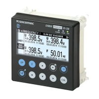
Example 5: Configuration of output 4 on inductive power factor
PFL with 0,5 for 4mA and
1 for 20mA.
DIRIS configuration (see instruction manual: 876 586):
Analogue output type = Out 2 20 mA TYPE = 4/20 (4 to 20mA)
Analogue output allocation = OUt 2 20 mA PAR = PFL (inductive power factor)
Value at 4mA = Out 2 20 mA LV = 500 (0,5)
Value at 20mA = Out 2 20 mA HV = 1000 (1)
Note: For the power factor, the values for 4 and 20mA must be programmed on 3 digits; therefore, for 0,5 enter the
value 500.
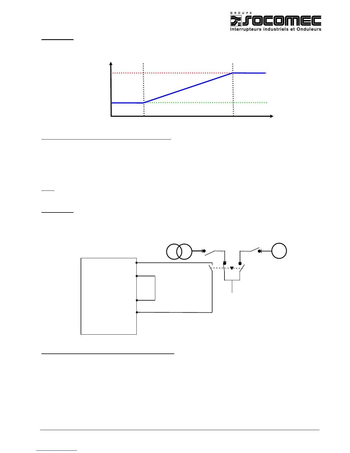
Example 6: Configuration of the analogue output 1 to provide a 30VDC optocoupler
supply to use with the inputs / outputs module . For example, to count the
number of changeover operations or control position (see §3.3)
DIRIS configuration (see instruction manual : 876 586) :
Analogue output type = Out 1 20mA TYPE = 30 V (30VDC)

 Loading...