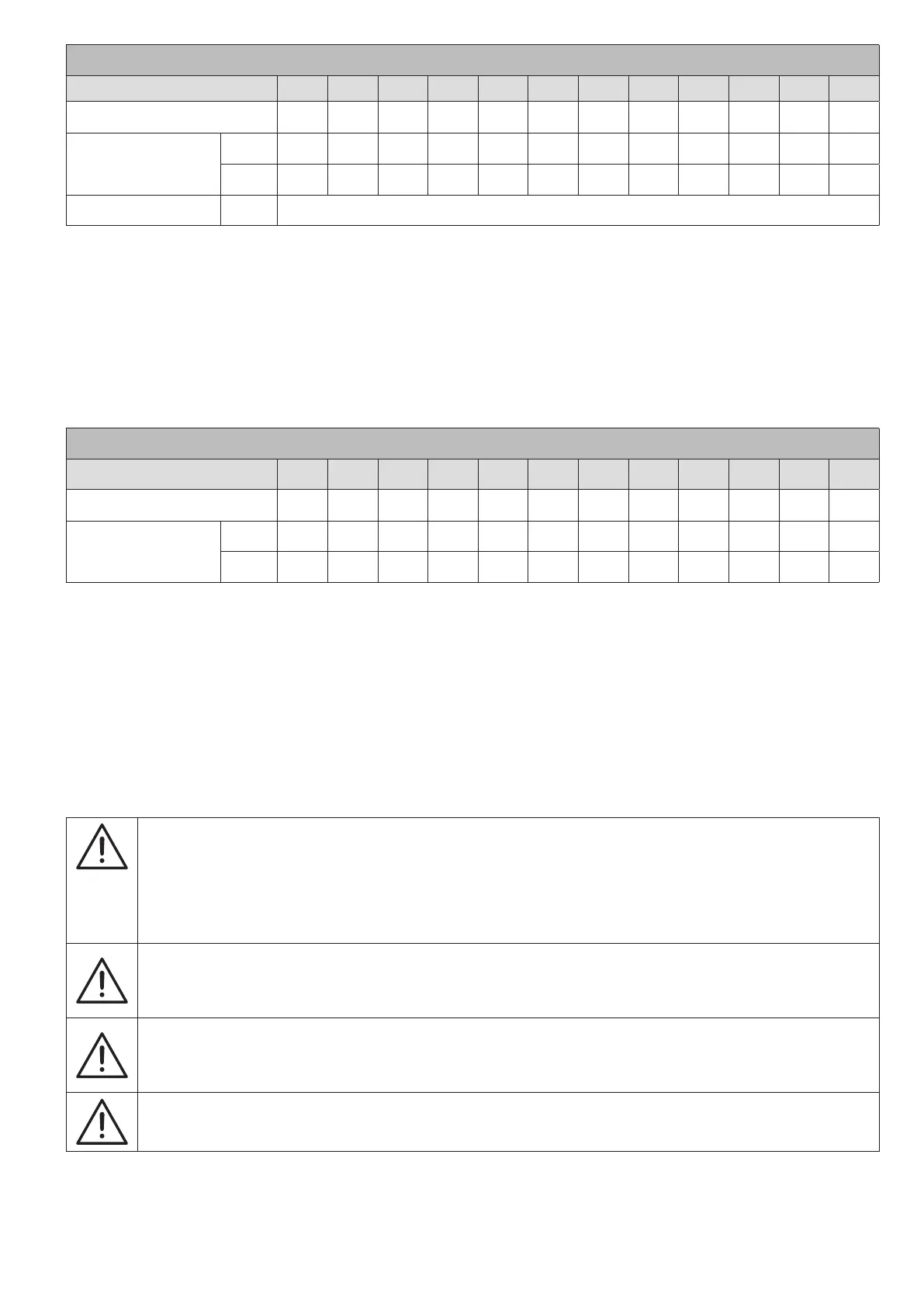
RECOMMENDED PROTECTION DEVICES - Rectifier
Number of Modules 2 3 4 5 6
7 8 9 10 11 12 13
N+1 redundant System Power (kW) 100+0
(1)
100+50 150+50 200+50 250+50 300+50 350+50 400+50 450+50 500+50 550+50 600+50
C Curve circuit breaker (A)
min. 200 320 400 630 630 630 800 1000 1000 1000 1250 1250
max. 1250 1250 1250 1250 1250 1250 1250 1250 1250 1250 1250 1250
Differential input
(2)
(A) min. 0,5
Circuit breaker switch recommended with magnetic intervention threshold ≥10 In (curve C). It is necessary to use a D
curve selective breaker if an optional external transformer is used. The min value depends on the size of the power cables
in the installation, while the max value is limited by the UPS cabinet.
(1). No redundancy
(2). Caution! Residual Current Detection (RCD) can only be used with a common input and auxiliary mains (configuration not recommended). It must be
placed upstream of the connection between input mains and auxiliary mains. Use type B fourpole selective (S) residual current detectors. Load leakage
currents are to be added to those generated by the UPS and during transitory phases (power failures and power returns) short current peaks may occur.
If loads with high leakage current are present, adjust the residual current protection. It is advisable in all cases to carry out a preliminary check on the
earth current leakage with the UPS installed and operational with the definitive load, so as to prevent the RCD tipping over.
RECOMMENDED PROTECTION DEVICES - Auxiliary mains
Number of Modules
2 3 4 5 6 7 8 9 10 11 12 13
N+1 redundant System Power (kW) 100+0
(1)
100+50 150+50 200+50 250+50 300+50 350+50 400+50 450+50 500+50 550+50 600+50
C Curve circuit breaker (A)
min. 200 320 400 630 630 630 800 1000 1000 1000 1000 1000
max. 1250 1250 1250 1250 1250 1250 1250 1250 1250 1250 1250 1250
Circuit breaker switch recommended with magnetic intervention threshold ≥10 In (curve C). It is necessary to use a D
curve selective breaker if an optional external transformer is used. The min value depends on the size of the power cables
in the installation, while the max value is limited by the UPS cabinet.
(1). No redundancy
The short-time withstand current (Icw) according to IEC 62040-1 is 20 kA rms for standard (C82) system, 35 kA rms for
high short-curcuit (C88) system, where 65 kA rms can be achieved using optional bypass.
Contact Socomec for detailed information.
NOTE!
To ensure the integrity of the bypass thyristors:
- I²t must be lower than 3920 kA²s and peak current must be lower than 28 kA for 20 ms in case of
standard system.
- I²t must be lower than 8000 kA²s and peak current must be lower than 40 kA for 20 ms in case of
system with extra bypass module.
Contact SOCOMEC for detailed information.
The UPS is designed for transient overvoltages in category III installations. If the UPS is part of
the building’s electrical circuit, or is likely to be subject to transient overvoltages in category IV
installations, additional external protection must be provided, either on the UPS or in the AC power
supply network powering the UPS.
WARNING!
Protective earthing conductor (PE) must have sufcient current-carrying capacity. The PE cable core
size must be chosen according to the PROTECTIVE CURRENT RATING of the earth circuit which
depends on the provision and location of protective overcurrent devices.
NOTE!
3-Phase 4-Wire Input Power is required. The unit can be installed in TN, TT and IT AC distribution
systems (IEC 60364-3).