STATYS
Jbus / Modbus serial link
6 OPMSTAJB0810-GB_01
ITALIANOENGLISH
5. 3. connectIonS and wIrIng
NOTE : there is only one connection per interface (RS232 or RS422 or RS485)
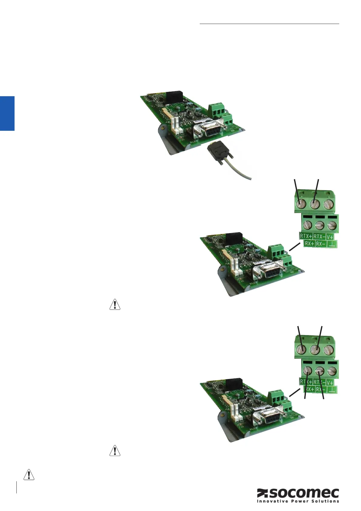
5. 3.1. RS232 connection:
– Standard PC connection
– Sub-D 9 pins connector
– Pin 2 : Rx
– Pin 3 : Tx
– Pin 5 : GND
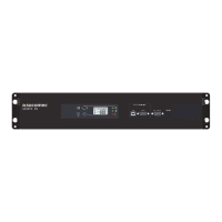
5. 3.2. Isolated RS485 connection
– 2 wires connection
– « dip-switch 1 » allows connecting the terminal resistor
– Isolation via “opto-coupler”
– 2 polarization resistors could be removed easily (if needed).
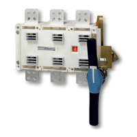
5. 3.3. Isolated RS422 connection
– 4 wires connection
– « dip-switch 1 and 2 » allows connecting the terminal
resistor
– Isolation via “opto-coupler”
– 4 polarization resistors could be removed easily (if needed).
rtx +
rtx -
tx -
rx -
tx +
rx +
Before making any connection, please check the cabling. A wrong connection or cabling can dam-
age the serial link interface.
the shield should be earthing at one point.
the shield should be earthing at one point.