SR5 MANUAL
10.3-ADJUSTMENT OF THE CAMBER AND OF THE CASTER
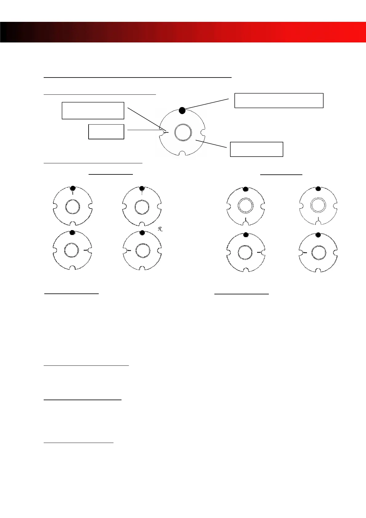
DESCRIPTION OF THE ECCENTRIC.
ADJUSTMENT OF THE CASTER
STANDARD ADJUSTMENT
(fig 1)
¾ 1° eccentrics place in high caster position (fig 1).
INCREASE THE CASTER
(fig 1)
¾ 2° eccentric in high caster (fig 1) position.
In extreme conditions, use 3°, 4° or more eccentrics.
REDUCE THE CASTER
(fig 2)
¾ 2°ou 3° eccentric (even more in extreme conditions) in low caster position.
diam. 4 mm pin on the fork
Marked slot
1 for 1°
Eccentric
HIGH CASTER
LOW CASTER
Eccentrics on top:
The mark is positioned on the opposite side of
the Ø4 mm pin.
(Towards the rear of the chassis) .
Eccentrics on top:
The mark is positioned in front of the Ø4 mm
pin.
(Towards the front of the chassis)
TOP
BOTTOM
FIG 1
FRON
REAR
LEF
FRON
TOP
BOTTOM
FIG 2
REAR
LEF
RIGH
RIGH
- 20 -