HYD 3000 ... 6000-EP User manual
Copyright © Shenzhen SOFARSOLAR Co., Ltd。
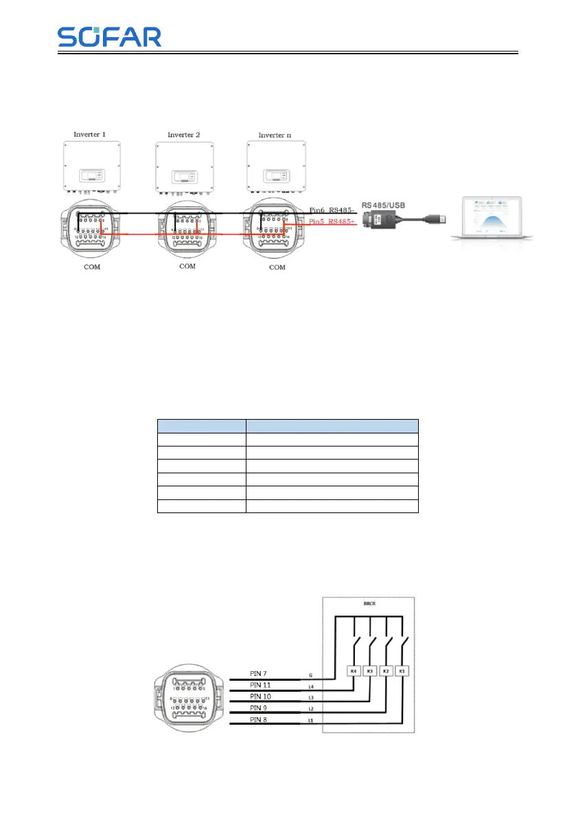
multiple inverters are connected via RS485 wires, set communication address to
differentiate the inverters , please refer to this manual<6.3.1System
setting→8.Communication Addr>)
Fig.4-11 RS485 connection(cascade of monitoring between inverters)
2. Logic interface
The logic interface pin definitions and circuit connections are as follows:
Logic interface pin are defined according to different standard requirements
(a)Logic interface for AS/NZS 4777.2:2015, also known as inverter demand
response modes (DRMs).
The inverter will detect and initiate a response to all supported demand
response commands within 2 s. The inverter will continue to respond while the
mode remains asserted.
Table 4-6 Function description of the DRMs terminal
(b)Logic interface for VDE-AR-N 4105:2018-11, is in order to control
and/or limit the inverter’s output power.
The inverter can be connected to a RRCR (Radio Ripple Control Receiver) in
order to dynamically limit the output power of all the inverters in the installation.
Fig.4-12 Inverter – RRCR Connection
Table 4-7 Function description of the terminal