14 / 47
4.1. Battery Connection
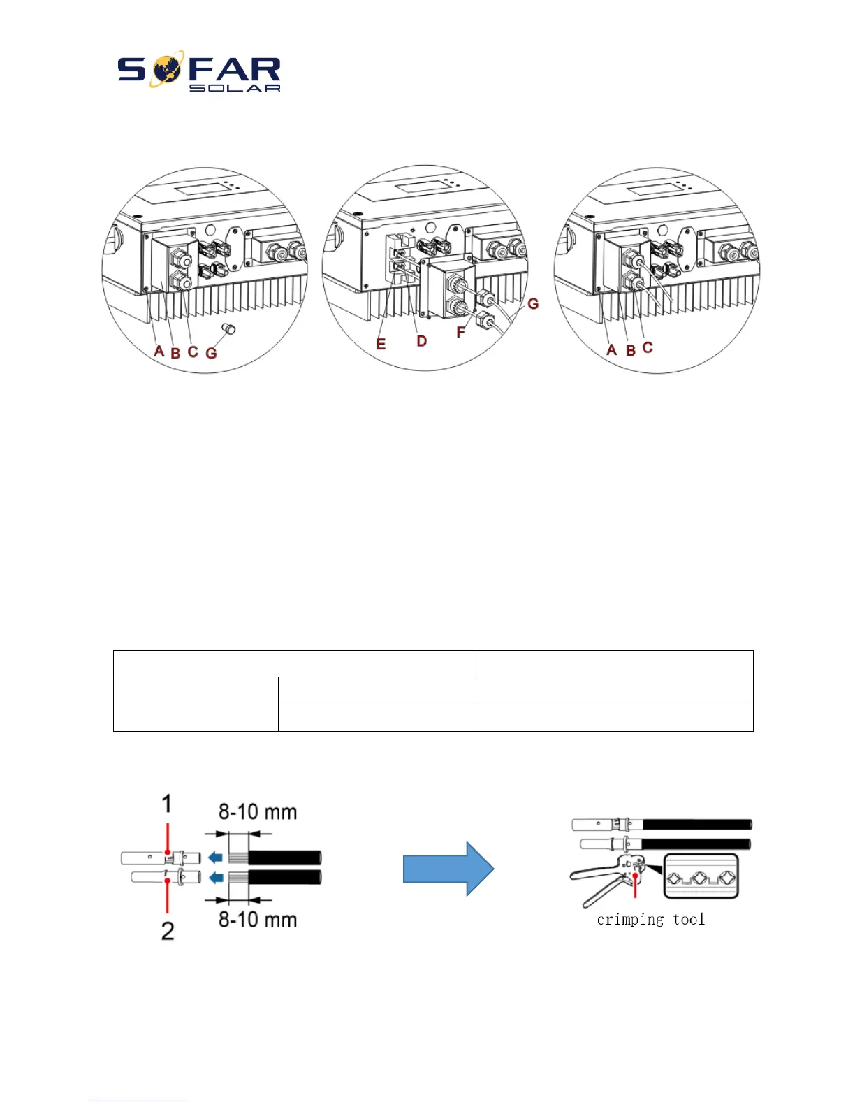
Fig. 6 Battery connection (Measure battery wires polarity/voltage before connection)
Step 1: Loosen 4 screws (A) using a screwdriver (Fig. 6);
Step 2: Remove the waterproof cover (B), loosen the cable gland (C), and then remove the stopper (G);
Step 3: Route the battery wires (F) through the cable gland, then connect battery wires using OT terminal (E);
Step 4: Fasten the waterproof cover using 4 screws.
4.2. PV Connection
Recommended DC input cable specifications
Procedure:
Step 1 Prepare PV positive and negative power cables
1. Positive metal contact 2. Negative metal contact
Fig. 7 prepare PV positive and negative power cables