6
PSX-NL4 Network Module - Operation Manual
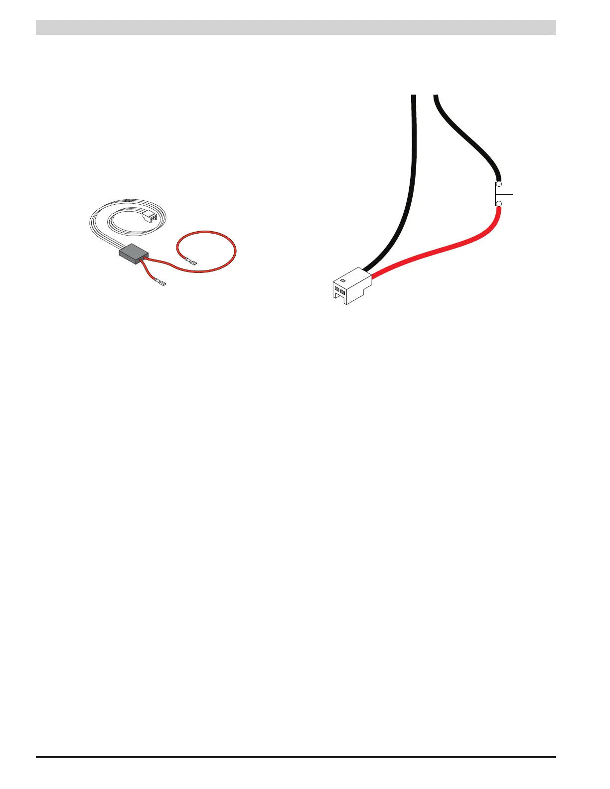
1.3.4 Connecting the Current Sensor(s)
Insert the current sensor in-line with the current to be mea-
sured, using the two red leads on the current sensor. (Fig-
ure 1.7) To read current in the correct polarity, the positive
current should flow from the longer lead to the shorter lead
on the current sensor. If current is being displayed in the
opposite polarity than expected, swap the short and long
red leads.
After connecting the red leads, connect the white cable to
the "H1" or "H2" connector on the PSX-NL4.
Figure 1.7 - Current Sensor
i Note: To utilize the PSX-NL4's Battery Condition bar
graph display or battery testing functions, the current sen-
sor must be placed in-line with one of the battery leads.
This precludes measuring any other currents with this cur-
rent sensor. When using the current sensor for the battery
measurement, connect the longer lead to the battery posi-
tive terminal and the shorter lead to the power supply posi-
tive battery connection so that battery DISCHARGE current
measures as POSITIVE. The current sensor connected to
the "H1" connector is for the battery connected to PSX #1.
the "H2" connector is for PSX #2.
1.3.5 Connecting the Event Input
Connect one end of the Event cable to the Event1 connec-
tor on the PSX-NL4 board and cut off the connector at the
other end of the Event cable. Connect the red and black
wires to the voltage to be monitored. If monitoring a relay
or switch contact (a common example would be the tamper
switch of the enclosure), an external voltage must be run
through the contact. Set the Event1 Input Invert Jumper as
required.
Example:
To monitor the NC tamper switch connect a positive voltage
(from the PSX power supply or distribution board) to one
lead of the tamper switch. Connect the other lead of the
tamper switch to the red (positive) lead of the Event cable.
Connect the black (negative) lead of the Event cable to the
negative (DC Common) of the voltage source. (Figure 1.8)
Since we want to cause an alert on the removal of voltage,
leave the Event1 Input Invert Jumper OFF.
–
+
9-28
VDC
Tamper
Switch
Black
Red
Event
Input
Figure 1.8 - Event1 Tamper Switch Wiring
1.3.6 Remote Temperature Sensor
The remote temperature sensor allows measuring a tem-
perature up to 6 feet away from the PSX-NL4 board. Plug
the sensor into J18 and run the sensor wire to the area or
device to be monitored.
1.3.7 Connecting the ADC (Voltmeter) Input
Connect one end of the ADC cable to the ADC1 input on the
PSX-NL4 board. Cut off the other end of the ADC cable and
connect it to the voltage source to be monitored, observing
polarity. The red wire is the positive input and the black wire
is the negative (DC Common) input. The ADC cable wiring
must be routed away from high voltages and the wire used
must be rated for the voltages and temperatures in the area
in which it is installed.
i Note: The voltage being measured by the ADC input
MUST be common grounded with the voltage source of the
PSX-NL4 board.