2
PSX-NL4 Network Module - Operation Manual
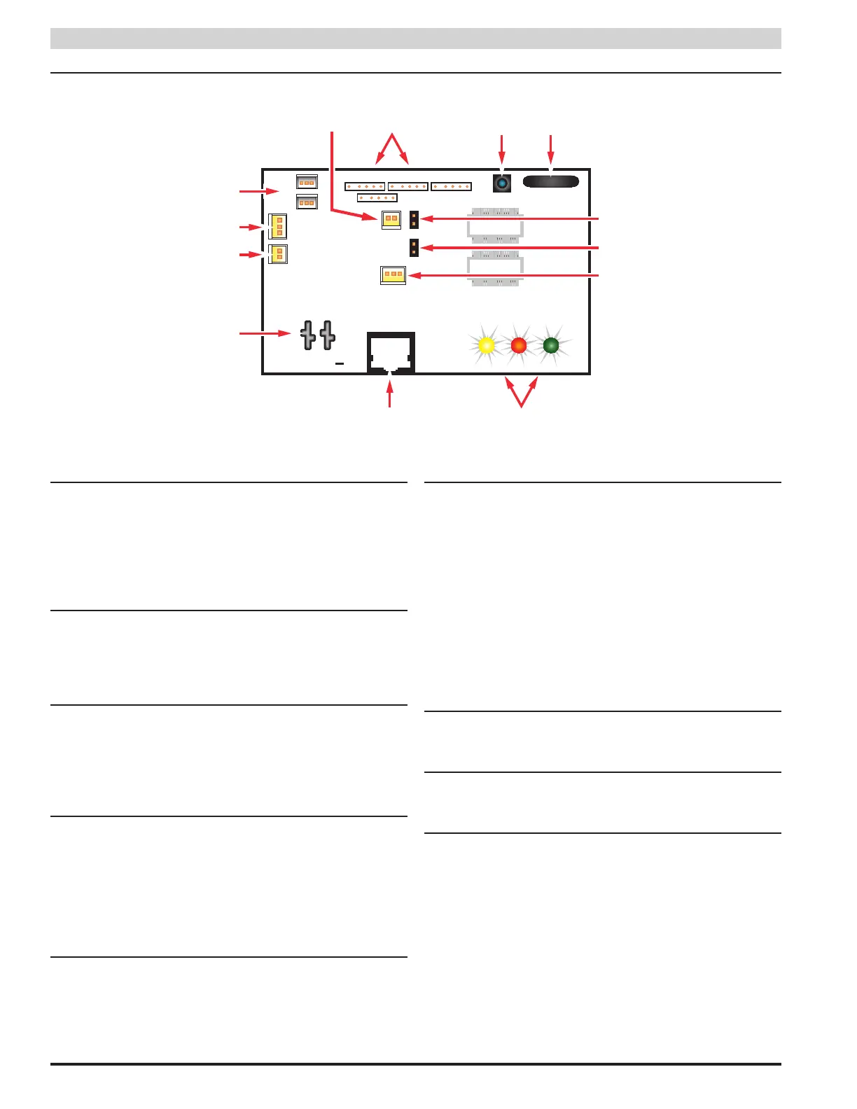
1.2 PSX-NL4 Network Communication Accessory Overview
RJ45
Input
Event 1
Reset
SYS DATA LINK
V V
+
ADC 1
J10
J18
H1
H2
Device 1
Device 4
Device 2
Device 3
J9
J8
The following are basic descriptions. Refer to the appropriate section for more detailed information.
1 PSX-NL4 - H1 and H2 Inputs (J12 & J16)
These are the connectors for the current sensors. Only
PSX-NL2 or PSX-NL4 current sensors should be plugged
into these connectors. The sensors have a range of +/-20A
and may be used to measure any current or may be used to
monitor approximate system battery health for PSX power
supplies connected to the PSX-NL4. See section 1.3.4
2 PSX-NL4 - Event 1 Input (J14)
This is the connector for the Event1 input. This input will
accept 9-30VDC to initiate an event alert. This input will only
indicate an active or inactive condition and will not measure
the voltage level. See section 1.3.5
3 PSX-NL4 - ADC1 Input (J15)
This is the Analog to Digital Converter (ADC) input, which
acts as a voltmeter. It accepts 0-30V and is used to mea-
sure positive or negative system voltages which are common
grounded with the PSX-NL4. The ADC cable wiring must be
routed away from high voltages. See section 1.3.7
4 PSX-NL4 - Input V+ & V- (J1 & J3)
This is the main power input for the PSX-NL4 board. This
input accepts 8 to 30VDC ONLY (Observe the polarity care-
fully) from any power supply.
i The voltage input of the PSX-NL4 must be connected di-
rectly to the DC1 output or to the V+/V- fastons (if present)
of the PSX power supply.
5 PSX-NL4 - Ethernet Connection (SK1)
This is the RJ45 jack for the network connection. The ethernet
cable is plugged into this jack. See section 1.3.2
6 PSX-NL4 - Status LED Indicators (D2, D3, D4)
These LEDs indicate the status of the Ethernet link to the
PSX-NL4 board.
LED Indicator:
Green (LINK) Lights when the PSX-NL4 is connected to a
network
Red (DATA) Flashes during data transfer
Yellow (SYS) Lights when the PSX-NL4 is fully booted up
and running. During the bootup process, this
LED may flash on and off several times. The
PSX-NL4 will not be able to be accessed until
this LED lights steady.
7 PSX-NL4 - External Temperature Sensor
This connector is for the external temperature sensor. See sec-
tion 1.3.6
8 PSX-NL4 - Not Used (J9)
This jumper provides no user function, do not place a jumper
on these pins.
9 PSX-NL4 - Event1 Input Invert Jumper (J8)
This jumper inverts the action of the Event 1 Input. See sec-
tion 1.3.5
Jumper Position:
ON Event 1 active when voltage is applied
OFF Event 1 active when voltage is removed