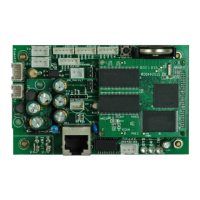
3
Installation and Operation
10 PSX-NL4 - Backup Battery (BT1)
This is the coin cell battery for maintaining the clock when
all power is removed from the PSX-NL4. The battery type is
CR2032.
11 PSX-NL4 - Factory Reset Button (SW1)
This button resets the User Name, Password, IP Address, and
SNMP Settings back to factory default. Typically used when IP
and/or login information has been lost.
12 PSX-NL4 - Device 1 - Device 4 (J4, J5, J11, J17)
These are the four serial links to the devices to be moni-
tored, such as PSX power supplies, or PSX-M8 boards. Data
is passed between the PSX-NL4 and the connected devices
through these links. Each PSX-NL4 board is limited to any
combination of a maximum of four, either two PSX power
supplies and two PSX-M8 boards or one PSX power supply
and three PSX-M8's. See section 1.3.3
13 PSX-NL4 - Control Outputs (J10)
This connector is for the two control outputs. These outputs
are open collector (transistor) low-current outputs for use with
RB Relay Boards, or other low-current inputs. The Control
Output cable wiring must be routed away from high voltages.
See Section 1.3.8
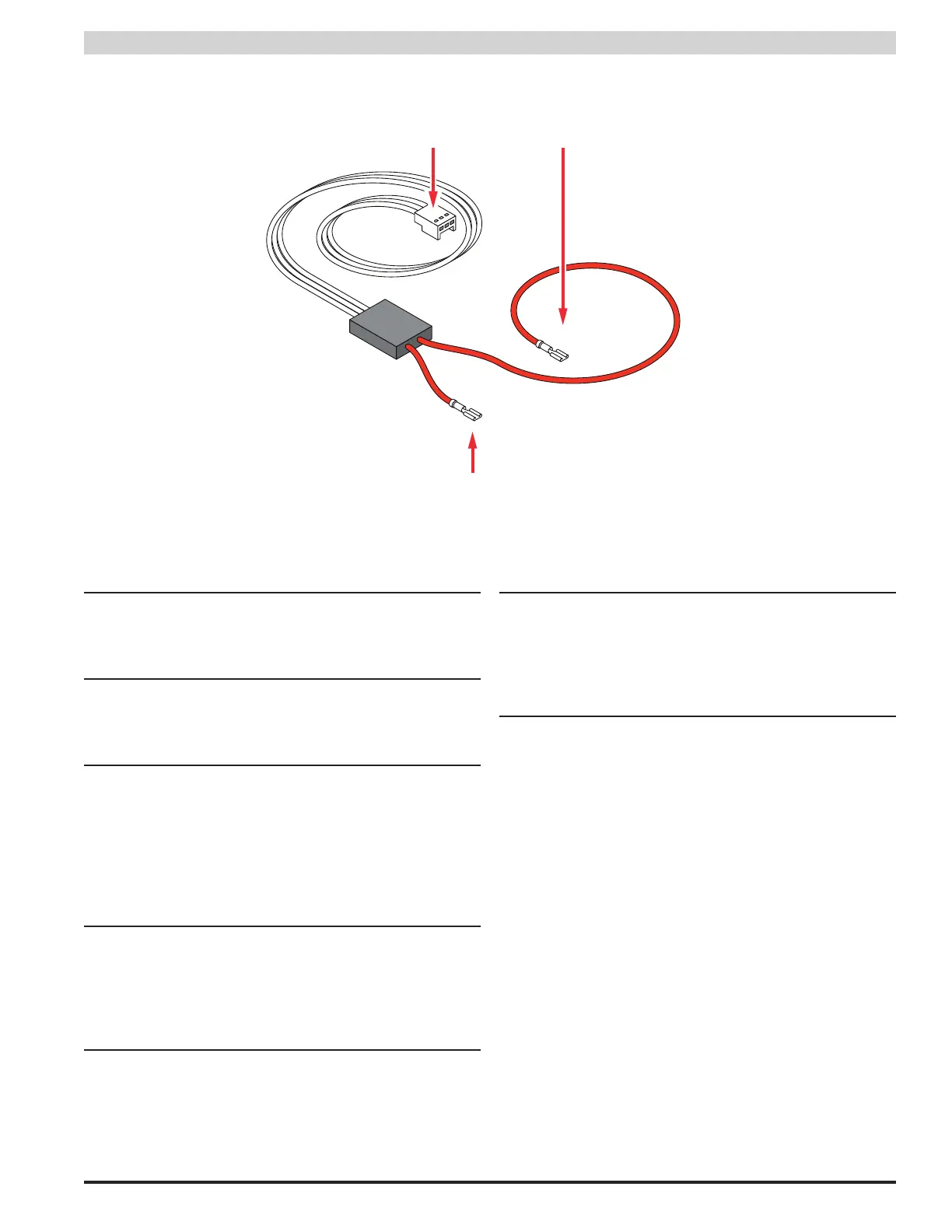
14 Current Sensor - Current Lead 1 (Short)
The short red lead connects in-line with the current to be
measured toward the more negative side of the current flow.
Positive current is measured when current flows from Cur-
rent Lead 2 (Long Lead) to Current Lead 1 (Short Lead). See
section 1.3.4
15 Current Sensor - Current Lead 2 (Long)
The long red lead connects in-line with the current to be
measured toward the more positive side of the current flow.
Positive current is measured when current flows from Cur-
rent Lead 2 (Long Lead) to Current Lead 1 (Short Lead). See
section 1.3.4
16 Current Sensor - Data Connector
This connector connects to the PSX-NL4 board's H1 or H2
input (J12 or J16) to provide the current reading to the PSX-
NL4. See section 1.3.4
Current Sensor Cable