4
PSX-NL4 Network Module - Operation Manual
1.3 Connecting the PSX-NL4 Network Communication Accessory
1.3.1 Making the Power Connections to the PSX-NL4
The DC power source for the PSX-NL4 is connected to the
INPUT (V+ & V-) fastons. The voltage of this source must
be between 8 and 30VDC and should be backed up with a
battery set or UPS to maintain communication during a loss
of primary AC voltage.
The power connections for the PSX-NL4 must connect di-
rectly to the DC1 output or the V+/V- faston connectors (if
present) of the FPO power supply. (Figure 1.4)
i Note: Do not power the PSX-NL4 through another acces-
sory board's output. (Figure 1.5)
1.3.2 Making the Ethernet Connection to the PSX-NL4
Plug the Ethernet cable into the RJ45 jack on the PSX-NL4
until the locking tab clicks. Connect the other end of the
Ethernet cable to the network.
i Note: The PSX-NL4 board should be configured via a
direct connection to a laptop or PC before connecting to the
network. See the Initial Configuration Section (Section 2) of
this manual for more details.
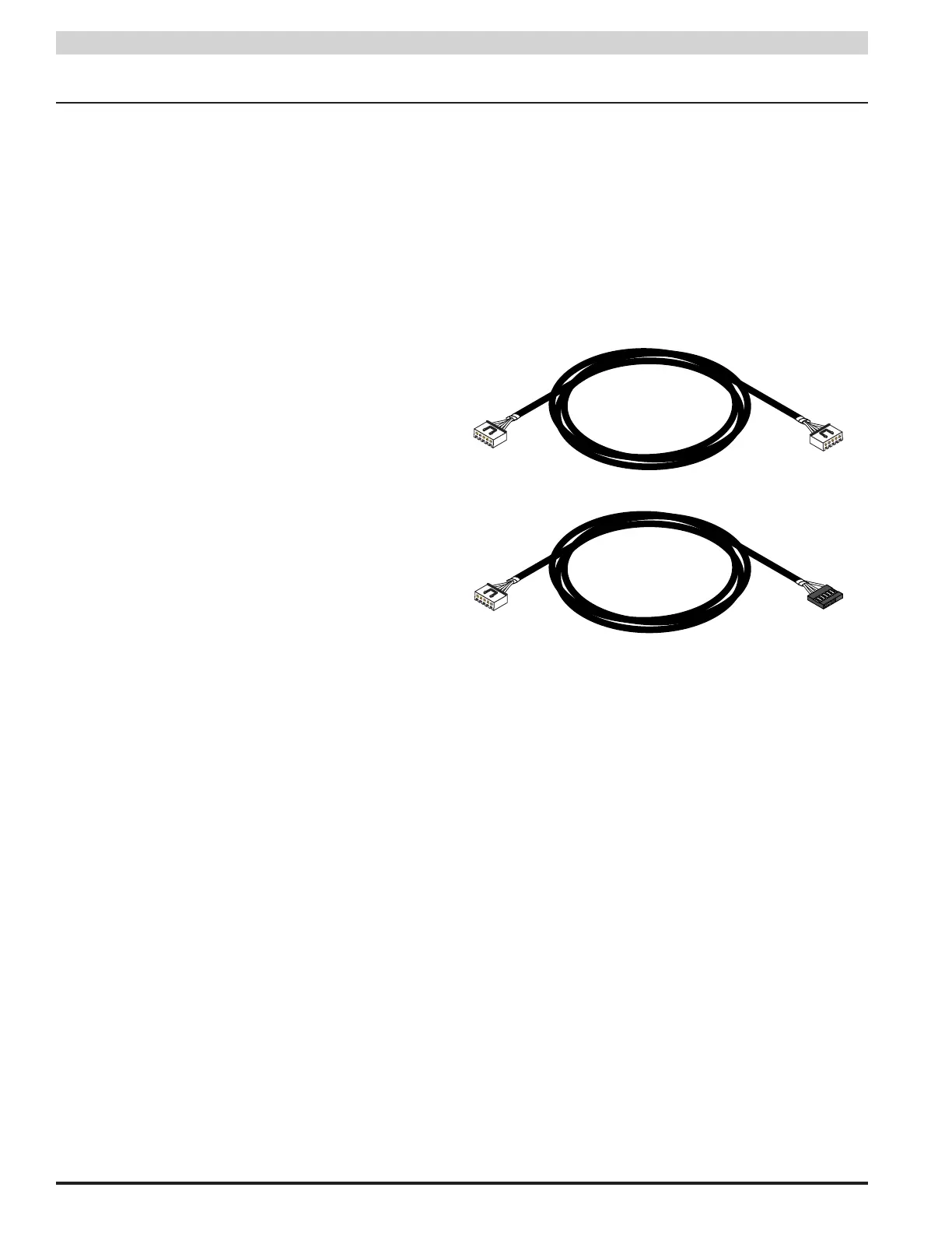
1.3.3 Connecting Devices to be Monitored to the PSX-NL4
Connect one end of the SPI cable to one of the "Device" con-
nectors on the PSX-NL4. Connect the other end to the Data-
Link (DL) connector of the device to be monitored (such as
a PSX - see the manual for the device being connected for
the location of the DL connector). If monitoring more than
one device, repeat this process for devices 2 through 4 as
appropriate. Note that both ends of these cables are keyed
and will only plug in one direction.
Figure 1.3 - The SPI Cable
There are two types of SPI connector currently in use. (Fig-
ure 1.3) The PSX-NL4 is supplied with two SPI cables for
use with the new-style connector (top drawing in Figure
1.3, above). If the device being connected to the PSX-NL4
uses the old-style connector, contact Software House for an
adaptor cable (bottom drawing in Figure 1.3, above)
If monitoring the battery health of PSX power supplies us-
ing the Current Sensors, the PSX-NL4 will assign Current
Sensor 1 to the PSX power supply connected to the lowest
numbered device connector. Current Sensor 2 will be as-
signed to the next PSX.
i Note: The PSX-NL4 provides four Device ports which
will accomodate a maximum of two PSX power supply
boards or a maximum of three PSX-M8/M8P boards.